HP ProLiant DL388 HP ProLiant DL388 G7 Server User Guide - Page 60
Expansion board options, Removing expansion slot covers
 |
View all HP ProLiant DL388 manuals
Add to My Manuals
Save this manual to your list of manuals |
Page 60 highlights
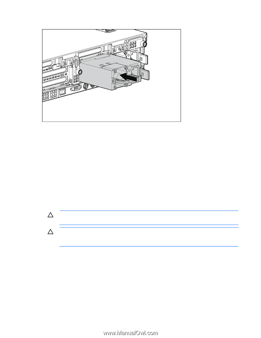
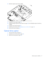
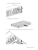
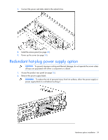
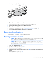
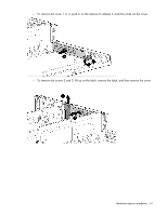
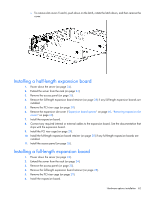
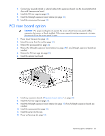
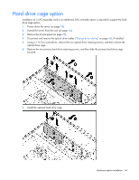
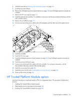
3. Install the power supply in the power supply bay. 4. Connect the power cord to the power supply. 5. Route the power cord through the power cord anchor or cable management arm. 6. Reposition the cable management arm into the operating position. 7. Connect the power cord to the power source. 8. Be sure that the power supply LED is green ("Rear panel LEDs and buttons" on page 12). 9. Verify that the corresponding power supply LED on the SID is green. Expansion board options The server supports PCI, PCI-X, and PCI Express expansion boards. Removing expansion slot covers CAUTION: To prevent damage to the server or expansion boards, power down the server and remove all AC power cords before removing or installing the PCI riser cage. CAUTION: For proper cooling do not operate the server without the access panel, baffles, expansion slot covers, or blanks installed. If the server supports hot-plug components, minimize the amount of time the access panel is open. 1. Power down the server (on page 24). 2. Extend the server from the rack (on page 24). 3. Remove the access panel (on page 25). 4. Remove the full-length expansion board retainer (on page 28) if any full-length expansion boards are installed. 5. Remove the PCI riser cage (on page 29). 6. Remove the expansion slot cover: Hardware options installation 60
-
 1
1 -
2
-
3
-
4
-
5
-
6
-
7
-
8
-
9
-
10
-
11
-
12
-
13
-
14
-
15
-
16
-
17
-
18
-
19
-
20
-
21
-
22
-
23
-
24
-
25
-
26
-
27
-
28
-
29
-
30
-
31
-
32
-
33
-
34
-
35
-
36
-
37
-
38
-
39
-
40
-
41
-
42
-
43
-
44
-
45
-
46
-
47
-
48
-
49
-
50
-
51
-
52
-
53
-
54
-
 55
55 -
 56
56 -
 57
57 -
 58
58 -
 59
59 -
 60
60 -
 61
61 -
 62
62 -
 63
63 -
 64
64 -
 65
65 -
66
-
67
-
68
-
69
-
70
-
71
-
72
-
73
-
74
-
75
-
76
-
77
-
78
-
79
-
80
-
81
-
82
-
83
-
84
-
85
-
86
-
87
-
88
-
89
-
90
-
91
-
92
-
93
-
94
-
95
-
96
-
97
-
98
-
99
-
100
-
101
-
102
-
103
-
104
-
105
-
106
-
107
-
108
-
109
-
110
-
111
-
112
-
113
-
114
-
115
-
116
-
117
-
118
-
119
-
120
-
121
-
122
-
123
-
124
-
125
-
126
-
127
 |
 |