HP ProLiant SL165s HP Power Interface Control (PPIC) Utility User Guide - Page 7
Calibrate and display power limits, Set power configuration mode
 |
View all HP ProLiant SL165s manuals
Add to My Manuals
Save this manual to your list of manuals |
Page 7 highlights
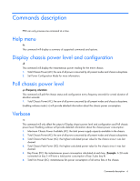
7. Set Power Configuration Mode for more information. Calibrate and display power limits -c: This command will force the system to idle state to get the lowest possible power configuration. Once the value has been obtained the system will display the updated information: 1. Maximum Chassis Power Available (AC): the total power supply capacity available in the chassis. 2. Minimum Chassis Power Achieved (AC): the lowest power achieved at idle with the current system configuration. 3. Power Limits (AC): the power range the Power Control Mode will guarantee full operation. 4. Set Power Configuration Mode for more information. NOTE: System performance will degrade while acquiring Power Profile. NOTE: When Power Control Configuration Mode is set to User Configurable (3), the system will return to the default Power Control Configuration Mode (1) after system calibration completes. The user is responsible for setting a new Power Control Configuration Mode and level. Set power configuration mode -s -mmode -lpower: This command will update the chassis Power Control Configuration Mode. The Power Management Control table shows the valid values for mode. Power is required when setting Power Control Configuration to User Configurable. Mode Configuration 0 No Redundancy Power throttling disabled. 1 AC Redundancy with throttling (Default mode) This provides Maximum Performance with PS Redundancy. Power control logic will only throttle the performance of each node in the case where the total power draw by the chassis attempts to exceed the power supply capacity. In this mode, the box is expected to survive an unexpected AC Power loss to one of the power supplies. 2 Full AC/DC Redundancy Power control logicl maintains a power cap value at the DC rating of a single power supply (Example: 460W, 750W, or 1200W), such that if one power supply experiences a DC or AC failure, the chassis remains on-line and operational. User must be cognizant of the minimum power consumption of the chassis and this must be less than the rating of a single power supply. 3 User Configurable (Available only with the LO100/iLO Advanced Pack) User specifies the power envelope for the chassis, within the capabilities of the HW installed. Before setting this mode, it is required that the user run PPIC's Calibrate and display power limits command to obtain the minimum and maximum power consumption envelope for the chassis. In order to avoid punitive performance due to throttling,do not set a User Configurable Power Control Mode limit value Commands description 7
-
 1
1 -
 2
2 -
 3
3 -
 4
4 -
 5
5 -
 6
6 -
 7
7 -
 8
8 -
 9
9 -
 10
10
 |
 |
