HP ProLiant SL210t HP ProLiant SL210t Gen8 Server User Guide - Page 51
Installing the Mini-SAS P420 LFF cable in a 1U node
 |
View all HP ProLiant SL210t manuals
Add to My Manuals
Save this manual to your list of manuals |
Page 51 highlights
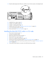
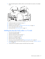
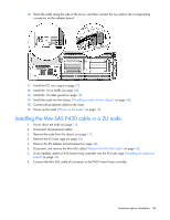
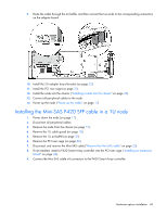
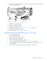
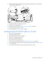
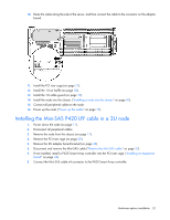
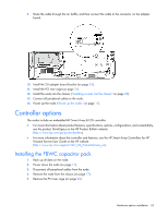
9. Route the cable through the air baffle, and then connect the two cable ends to the corresponding connectors on the adapter board. 10. Install the 2U adapter board bracket (on page 23). 11. Install the PCI riser cage (on page 21). 12. Install the node into the chassis ("Installing a node into the chassis" on page 30). 13. Connect all peripheral cables to the node. 14. Power up the node ("Power up the nodes" on page 17). Installing the Mini-SAS P420 LFF cable in a 1U node 1. Power down the node (on page 17). 2. Disconnect all peripheral cables. 3. Remove the node from the chassis (on page 17). 4. Remove the 1U cable guard (on page 18). 5. Remove the 1U air baffle (on page 27). 6. Remove the PCI riser cage (on page 20). 7. Disconnect and remove the Mini-SAS cable ("Remove the Mini-SAS cable" on page 23). 8. If not installed, install a P420 Smart Array controller into the PCI riser cage ("Installing an expansion board" on page 42). 9. Connect the Mini-SAS cable x4 connector to the P420 Smart Array controller. Hardware options installation 51
-
 1
1 -
2
-
3
-
4
-
5
-
6
-
7
-
8
-
9
-
10
-
11
-
12
-
13
-
14
-
15
-
16
-
17
-
18
-
19
-
20
-
21
-
22
-
23
-
24
-
25
-
26
-
27
-
28
-
29
-
30
-
31
-
32
-
33
-
34
-
35
-
36
-
37
-
38
-
39
-
40
-
41
-
42
-
43
-
44
-
45
-
 46
46 -
 47
47 -
 48
48 -
 49
49 -
 50
50 -
 51
51 -
 52
52 -
 53
53 -
 54
54 -
 55
55 -
 56
56 -
57
-
58
-
59
-
60
-
61
-
62
-
63
-
64
-
65
-
66
-
67
-
68
-
69
-
70
-
71
-
72
-
73
-
74
-
75
-
76
-
77
-
78
-
79
-
80
-
81
-
82
-
83
-
84
-
85
-
86
-
87
-
88
-
89
-
90
-
91
-
92
-
93
-
94
-
95
-
96
-
97
-
98
-
99
-
100
-
101
 |
 |
