HP R12000/3 UPS R6000 Models User Guide - Page 12
Rear Panel, Rear panel configuration
 |
View all HP R12000/3 manuals
Add to My Manuals
Save this manual to your list of manuals |
Page 12 highlights
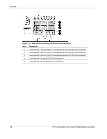
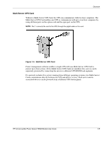
Overview Rear Panel The rear panel configuration of the UPS is shown in Figure 1-2 and Figure 1-3. Figure 1-2: Rear panel configuration Item Description 1 Communications ports 2 Manual Bypass switch 3 Input terminal block 4 16 A receptacles 5 10 A receptacles 6 Circuit breakers for segments (left to right) 1, 2, 3, 4, and 5 7 Circuit breakers for (left to right) • Segments 1 and 4 • Segment 2 • Segments 3 and 5 8 REPO port HP Uninterruptible Power System R6000 Models User Guide 1-3
-
 1
1 -
2
-
3
-
4
-
5
-
6
-
 7
7 -
 8
8 -
 9
9 -
 10
10 -
 11
11 -
 12
12 -
 13
13 -
 14
14 -
 15
15 -
 16
16 -
 17
17 -
18
-
19
-
20
-
21
-
22
-
23
-
24
-
25
-
26
-
27
-
28
-
29
-
30
-
31
-
32
-
33
-
34
-
35
-
36
-
37
-
38
-
39
-
40
-
41
-
42
-
43
-
44
-
45
-
46
-
47
-
48
-
49
-
50
-
51
-
52
-
53
-
54
-
55
-
56
-
57
-
58
-
59
-
60
-
61
-
62
-
63
-
64
-
65
-
66
-
67
-
68
 |
 |

Overview
HP Uninterruptible Power System R6000 Models User Guide
1-3
Rear Panel
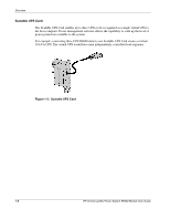
The rear panel configuration of the UPS is shown in Figure 1-2 and Figure 1-3.
Figure 1-2:
Rear panel configuration
Item
Description
1
Communications ports
2
Manual Bypass switch
3
Input terminal block
4
16 A receptacles
5
10 A receptacles
6
Circuit breakers for segments (left to right) 1, 2, 3, 4, and 5
7
Circuit breakers for (left to right)
•
Segments 1 and 4
•
Segment 2
•
Segments 3 and 5
8
REPO port