HP Scitex FB10000 Geffen TS Error 66008 - Page 5
The MM4331 B&R module [1MM3] is faulty – replace module
 |
View all HP Scitex FB10000 manuals
Add to My Manuals
Save this manual to your list of manuals |
Page 5 highlights
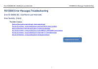
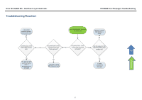
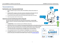
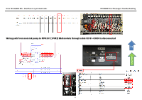
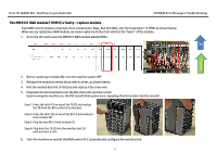
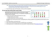
Error ID: 66008: IDS - Overflow in cyan main tank. FB10000 Error Messages Troubleshooting The MM4331 B&R module [1MM3] is faulty - replace module Each B&R control module comprises three components: Base, Bus Unit (BU), and Terminal block (12 PINS) as shown below. When we say replacing a B&R module, we mean replacing its Bus Unit which is the "heart" of the module. 1. Go to the LEC and locate the MM4331 B&R module labeled MM3. Top Flowchart 2. Before replacing a module BU, turn the machine power OFF. 3. Release the module terminal block with its wires, as shown below. 4. Pull the module Bus Unit of its base and replace it by a new one. 5. Plug back the terminal block into the Bus Unit until you hear a click. Upon turning the machine on, the R/E led will blink green once, signaling that it has detected the new BU. Step 1: Press the latch (1) on top of the TB (2) and unplug the TB from the BU to which it is attached. Step 2: Press the latch (5) on top of the BU (3) and unplug it from its base (4). Step 3: Plug the new BU (3) into its base (4). Step 4: Plug back the TB (2) into the new Bus Unit (3) until you hear a click. 6. Turn the machine on and let the B&R control PLC automatically configure the new Bus Unit. 5
-
 1
1 -
 2
2 -
 3
3 -
 4
4 -
 5
5 -
 6
6 -
 7
7 -
 8
8 -
 9
9
 |
 |
