HP Server rp2400 Hardware Manual - rp24xx, Customer Viewable - Page 189
DC-DC Converter Replacement, Step 1., CPU MHz, Master, Slave
 |
View all HP Server rp2400 manuals
Add to My Manuals
Save this manual to your list of manuals |
Page 189 highlights
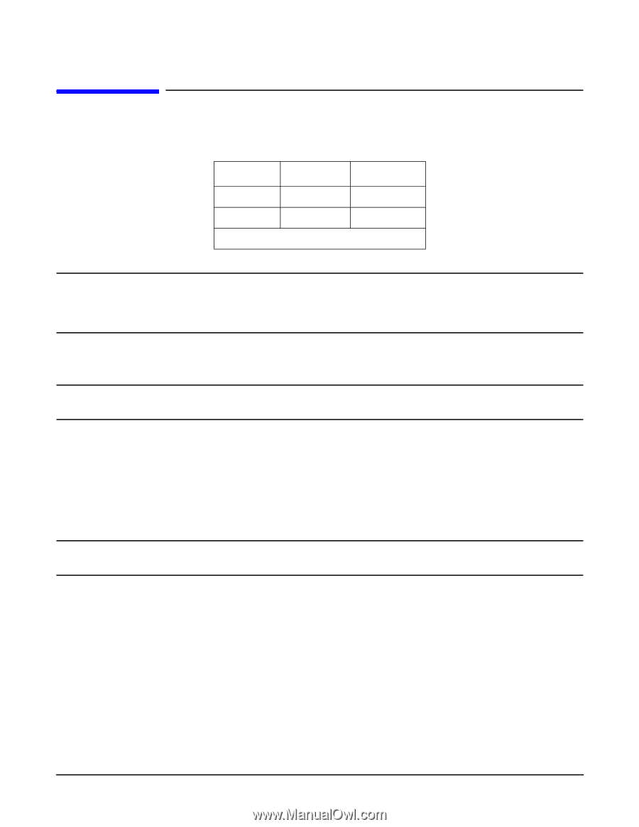
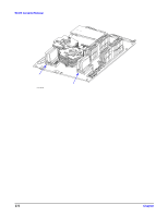
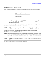
DC-DC Converter Replacement DC-DC Converter Replacement DC-DC Converter boards and one or two slave boards (depending on the CPU speed) are required to power each CPU. CPU MHz Master Slave 440 1 1 550* 1 2 * When available NOTE Each CPU requires a DC-DC Converter and slave(s) to operate. When CPUs are upgraded or replaced, ensure that the accompanying DC-DC Converter and slave(s) are changed. When returning replaced CPUs to Hewlett-Packard, ensure that the accompanying DC-DC Converter and slave(s) are returned also. The converter boards stand on edge in slots and are located immediately behind the Power Supply on the left and right sides of the System Board, in front of the CPU assemblies. CAUTION DC-DC converter boards are not "hot-swap" or "hot-plug" units. Shut the server down and unplug the electrical connection prior to removing or replacing DC-DC converter boards. To replace a DC-DC Converter board and its slave(s) from the server, perform the following steps: Step 1. Grasp the board by the left and right edges. Step 2. Align the board connector with the slot. The slot and board are keyed so that the board will only fit one way. Place your thumbs on the top edge of the board, near the left and right sides, and push the board straight down into its slot until either an audible "click" is heard, or the levers close and seat into the slots in the side edges of the board CAUTION DO NOT press hard on the left/right levers or they will break. Levers provide vertical stability, only. The following graphic shows a DC-DC converter board and slave(s). Chapter 273
-
 1
1 -
2
-
3
-
4
-
5
-
6
-
7
-
8
-
9
-
10
-
11
-
12
-
13
-
14
-
15
-
16
-
17
-
18
-
19
-
20
-
21
-
22
-
23
-
24
-
25
-
26
-
27
-
28
-
29
-
30
-
31
-
32
-
33
-
34
-
35
-
36
-
37
-
38
-
39
-
40
-
41
-
42
-
43
-
44
-
45
-
46
-
47
-
48
-
49
-
50
-
51
-
52
-
53
-
54
-
55
-
56
-
57
-
58
-
59
-
60
-
61
-
62
-
63
-
64
-
65
-
66
-
67
-
68
-
69
-
70
-
71
-
72
-
73
-
74
-
75
-
76
-
77
-
78
-
79
-
80
-
81
-
82
-
83
-
84
-
85
-
86
-
87
-
88
-
89
-
90
-
91
-
92
-
93
-
94
-
95
-
96
-
97
-
98
-
99
-
100
-
101
-
102
-
103
-
104
-
105
-
106
-
107
-
108
-
109
-
110
-
111
-
112
-
113
-
114
-
115
-
116
-
117
-
118
-
119
-
120
-
121
-
122
-
123
-
124
-
125
-
126
-
127
-
128
-
129
-
130
-
131
-
132
-
133
-
134
-
135
-
136
-
137
-
138
-
139
-
140
-
141
-
142
-
143
-
144
-
145
-
146
-
147
-
148
-
149
-
150
-
151
-
152
-
153
-
154
-
155
-
156
-
157
-
158
-
159
-
160
-
161
-
162
-
163
-
164
-
165
-
166
-
167
-
168
-
169
-
170
-
171
-
172
-
173
-
174
-
175
-
176
-
177
-
178
-
179
-
180
-
181
-
182
-
183
-
 184
184 -
 185
185 -
 186
186 -
 187
187 -
 188
188 -
 189
189 -
 190
190 -
 191
191 -
 192
192 -
 193
193 -
 194
194 -
195
-
196
-
197
-
198
-
199
-
200
-
201
-
202
 |
 |