HP Spectre 13-h210dx HP Split 13 x2 PC Maintenance and Service Guide - Page 78
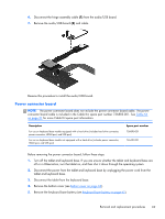
Disconnect the hinge assembly cable, Remove the power connector board
 |
View all HP Spectre 13-h210dx manuals
Add to My Manuals
Save this manual to your list of manuals |
Page 78 highlights
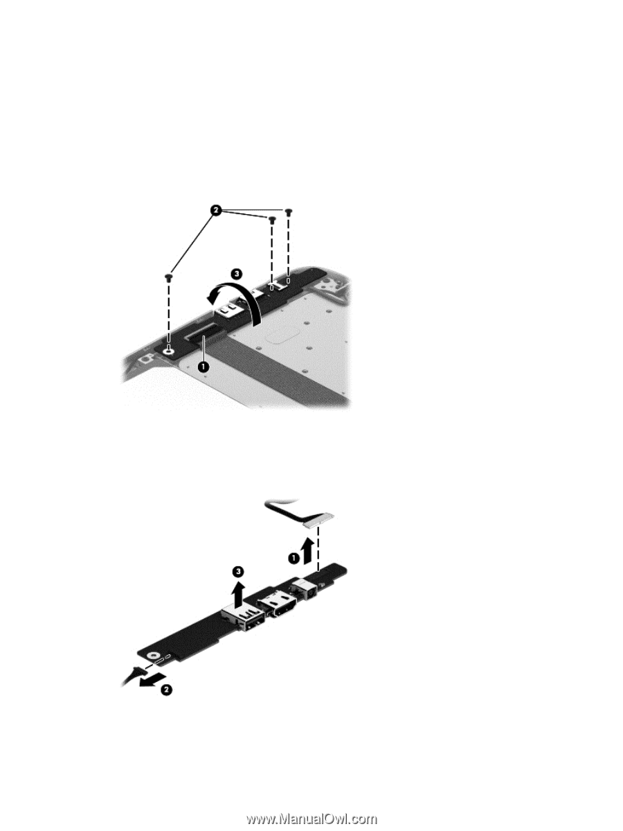
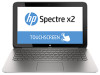
Remove the power connector board: 1. Release the power connector board ZIF connector (1) to which the audio/USB board cable is attached, and then disconnect the audio/USB board cable from the power connector board. 2. Remove the three Phillips PM2.0×3.0 screws (2) that secure the power connector board to the keyboard/top cover. 3. Lift the right side of the power connector board, and then swing it up (3) and to the left until it rests upside down on the right side of the keyboard/top cover. 4. Disconnect the hinge assembly cable (1) from the power connector board. 5. Disconnect the hard drive cable (2) from the power connector board. 6. Remove the power connector board (3). Reverse this procedure to install the power connector board. 70 Chapter 4 Removal and replacement preliminary requirements
-
 1
1 -
2
-
3
-
4
-
5
-
6
-
7
-
8
-
9
-
10
-
11
-
12
-
13
-
14
-
15
-
16
-
17
-
18
-
19
-
20
-
21
-
22
-
23
-
24
-
25
-
26
-
27
-
28
-
29
-
30
-
31
-
32
-
33
-
34
-
35
-
36
-
37
-
38
-
39
-
40
-
41
-
42
-
43
-
44
-
45
-
46
-
47
-
48
-
49
-
50
-
51
-
52
-
53
-
54
-
55
-
56
-
57
-
58
-
59
-
60
-
61
-
62
-
63
-
64
-
65
-
66
-
67
-
68
-
69
-
70
-
71
-
72
-
 73
73 -
 74
74 -
 75
75 -
 76
76 -
 77
77 -
 78
78 -
 79
79 -
 80
80 -
 81
81 -
 82
82 -
 83
83 -
84
-
85
-
86
-
87
-
88
-
89
-
90
-
91
-
92
-
93
-
94
-
95
-
96
-
97
-
98
-
99
-
100
-
101
-
102
 |
 |