HP Spectre XT Ultrabook 13-2157nr HP SpectreXT Maintenance and Service Guide - Page 45
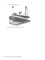
Fan, RJ-45 module cover, Remove the 2 Phillips PM 2.0x4.0 screws securing the fan to the top cover
 |
View all HP Spectre XT Ultrabook 13-2157nr manuals
Add to My Manuals
Save this manual to your list of manuals |
Page 45 highlights
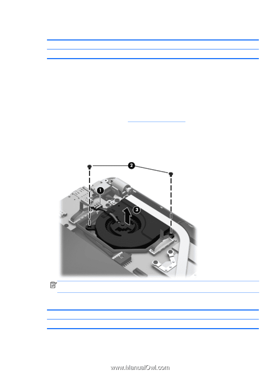
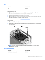
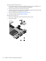
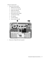
Fan Description Fan Spare part number 692890-001 Before removing the fan: 1. Shut down the computer. If you are unsure whether the computer is off or in Hibernation, turn the computer on, and then shut it down through the operating system. 2. Disconnect all external devices connected to the computer. 3. Disconnect the power from the computer by first unplugging the power cord from the AC outlet and then unplugging the AC adapter from the computer. 4. Remove the base enclosure (see Base enclosure on page 29). Remove the fan: 1. Disconnect the fan cable (1). 2. Remove the 2 Phillips PM 2.0x4.0 screws securing the fan to the top cover (2), and then lift the fan upwards (3). NOTE: You may need to remove the piece of tape on the underside of the heat sink that secures the fan to the unit. RJ-45 module cover Description RJ-45 module cover (plastics kit) Spare part number 689948-001 Component replacement procedures 37
-
 1
1 -
2
-
3
-
4
-
5
-
6
-
7
-
8
-
9
-
10
-
11
-
12
-
13
-
14
-
15
-
16
-
17
-
18
-
19
-
20
-
21
-
22
-
23
-
24
-
25
-
26
-
27
-
28
-
29
-
30
-
31
-
32
-
33
-
34
-
35
-
36
-
37
-
38
-
39
-
 40
40 -
 41
41 -
 42
42 -
 43
43 -
 44
44 -
 45
45 -
 46
46 -
 47
47 -
 48
48 -
 49
49 -
 50
50 -
51
-
52
-
53
-
54
-
55
-
56
-
57
-
58
-
59
-
60
-
61
-
62
-
63
-
64
-
65
-
66
-
67
-
68
-
69
-
70
-
71
-
72
-
73
-
74
-
75
-
76
-
77
-
78
-
79
-
80
-
81
-
82
-
83
-
84
-
85
-
86
-
87
-
88
-
89
-
90
 |
 |