HP Split 13-f000 HP Split 13 x2 PC Maintenance and Service Guide - Page 46
Removal and replacement procedures, Tablet component replacement procedures, Back cover
 |
View all HP Split 13-f000 manuals
Add to My Manuals
Save this manual to your list of manuals |
Page 46 highlights
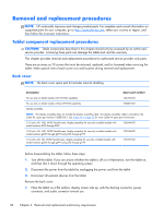
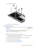
Removal and replacement procedures NOTE: HP continually improves and changes product parts. For complete and current information on supported parts for your computer, go to http://partsurfer.hp.com, select your country or region, and then follow the on-screen instructions. Tablet component replacement procedures CAUTION: Tablet components described in this chapter should only be accessed by an authorized service provider. Accessing these parts can damage the tablet and void the warranty. This chapter provides removal and replacement procedures for authorized service provider only parts. There are as many as 29 screws that must be removed, replaced, and/or loosened when servicing the tablet. Make special note of each screw size and location during removal and replacement. Back cover NOTE: The back cover spare part kit includes internal shielding. Description Spare part number For use only on tablet models with WWAN capability 746492-001 For use only on tablet models without WWAN capability 736881-001 Display assembly: NOTE: The display assembly does not include the display assembly cable. The display assembly cable is included in the Cable Kit, spare part number 736883-001. See Cable Kit on page 23 for more Cable Kit spare part information. 13.3-inch, AG, FHD, WLED TouchScreen, display assembly for use only on tablet models with model numbers f000 through f099 765844-001 13.3-inch, AG, FHD, WLED TouchScreen, display assembly for use only on tablet models with model numbers g200 through g299 and g100 through g199 737696-001 13.3-inch, AG, HD, WLED TouchScreen, display assembly for use only on tablet models with model numbers g200 through g299 and g100 through g199 737697-001 Before disassembling the tablet, follow these steps: 1. Turn off the tablet. If you are unsure whether the tablet is off or in Hibernation, turn the tablet on, and then shut it down through the operating system. 2. Disconnect the power from the tablet by unplugging the power cord from the tablet. 3. Disconnect all external devices from the tablet. Remove the back cover: 1. Place the tablet on a flat surface, display screen side up, with the docking connector, power connector, and audio connector toward you. 38 Chapter 4 Removal and replacement preliminary requirements
-
 1
1 -
2
-
3
-
4
-
5
-
6
-
7
-
8
-
9
-
10
-
11
-
12
-
13
-
14
-
15
-
16
-
17
-
18
-
19
-
20
-
21
-
22
-
23
-
24
-
25
-
26
-
27
-
28
-
29
-
30
-
31
-
32
-
33
-
34
-
35
-
36
-
37
-
38
-
39
-
40
-
 41
41 -
 42
42 -
 43
43 -
 44
44 -
 45
45 -
 46
46 -
 47
47 -
 48
48 -
 49
49 -
 50
50 -
 51
51 -
52
-
53
-
54
-
55
-
56
-
57
-
58
-
59
-
60
-
61
-
62
-
63
-
64
-
65
-
66
-
67
-
68
-
69
-
70
-
71
-
72
-
73
-
74
-
75
-
76
-
77
-
78
-
79
-
80
-
81
-
82
-
83
-
84
-
85
-
86
-
87
-
88
-
89
-
90
-
91
-
92
-
93
-
94
-
95
-
96
-
97
-
98
-
99
-
100
-
101
-
102
-
103
-
104
-
105
-
106
-
107
 |
 |