HP Split 13-f000 HP Split 13 x2 PC Maintenance and Service Guide - Page 76
Keyboard base component replacement procedures, Bottom cover
 |
View all HP Split 13-f000 manuals
Add to My Manuals
Save this manual to your list of manuals |
Page 76 highlights
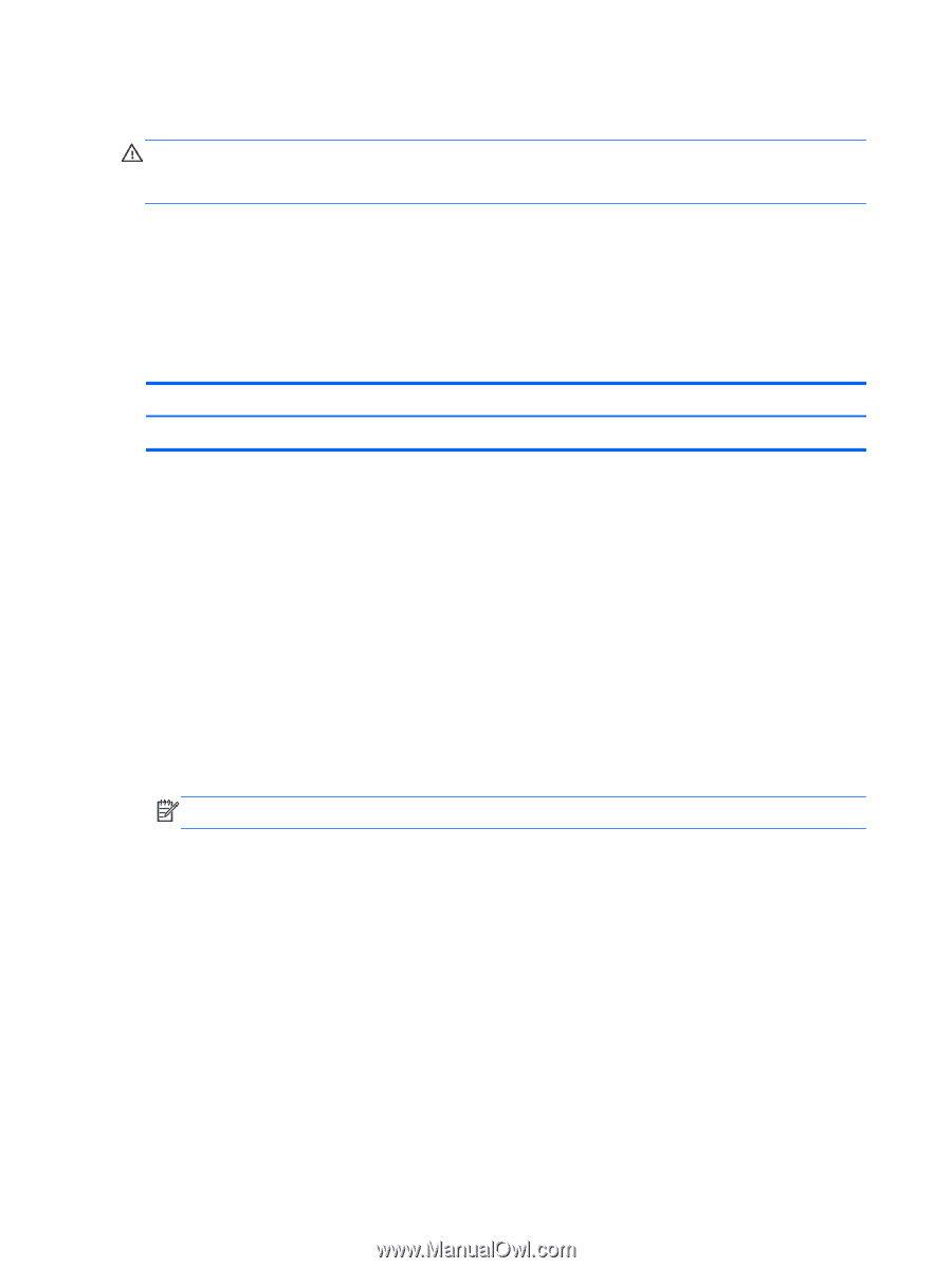
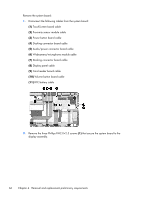
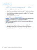
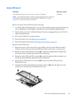
Keyboard base component replacement procedures CAUTION: Keyboard base components described in this chapter should only be accessed by an authorized service provider. Accessing these parts can damage the keyboard base and void the warranty. This chapter provides removal and replacement procedures for authorized service provider only parts. There are as many as 35 screws that must be removed, replaced, and/or loosened when servicing the keyboard base. Make special note of each screw size and location during removal and replacement. Bottom cover Description Bottom cover (includes rubber feet) Spare part number 736882-001 Before disassembling the keyboard base, follow these steps: 1. Turn off the tablet and keyboard base. If you are unsure whether the tablet and keyboard base are off or in Hibernation, turn the tablet on, and then shut it down through the operating system. 2. Disconnect the power from the tablet and keyboard base by unplugging the power cord from the tablet and keyboard base. 3. Disconnect the tablet from the keyboard base. Remove the bottom cover: 1. Remove the four Phillips PM2.0×4.25 screws (1) that secure the bottom cover to the keyboard/ top cover. 2. Remove the rubber feet (2). NOTE: The rubber feet are available in the Rubber Kit, spare part number 736897-001. 68 Chapter 4 Removal and replacement preliminary requirements
-
 1
1 -
2
-
3
-
4
-
5
-
6
-
7
-
8
-
9
-
10
-
11
-
12
-
13
-
14
-
15
-
16
-
17
-
18
-
19
-
20
-
21
-
22
-
23
-
24
-
25
-
26
-
27
-
28
-
29
-
30
-
31
-
32
-
33
-
34
-
35
-
36
-
37
-
38
-
39
-
40
-
41
-
42
-
43
-
44
-
45
-
46
-
47
-
48
-
49
-
50
-
51
-
52
-
53
-
54
-
55
-
56
-
57
-
58
-
59
-
60
-
61
-
62
-
63
-
64
-
65
-
66
-
67
-
68
-
69
-
70
-
 71
71 -
 72
72 -
 73
73 -
 74
74 -
 75
75 -
 76
76 -
 77
77 -
 78
78 -
 79
79 -
 80
80 -
 81
81 -
82
-
83
-
84
-
85
-
86
-
87
-
88
-
89
-
90
-
91
-
92
-
93
-
94
-
95
-
96
-
97
-
98
-
99
-
100
-
101
-
102
-
103
-
104
-
105
-
106
-
107
 |
 |