HP StorageWorks 2000fc HP StorageWorks MSA2312/2324fc Installation instruction - Page 2
Step 4: Power Cords, Step 5: Powering up, Step 6: Con, gure your MSA, Additional information sites
 |
View all HP StorageWorks 2000fc manuals
Add to My Manuals
Save this manual to your list of manuals |
Page 2 highlights
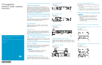
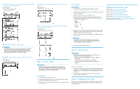
MSA2312/2324fc dual-controller enclosure and three MSA2000 3.5" 12-drive enclosures (maximum) Cables Required: • Mini SAS 4x to SAS 4x (2) • SAS 4x to SAS 4x (4) MSA2324fc dual-controller enclosure and one MSA70 drive enclosure Cables Required: • Mini SAS 4x to Mini SAS 4x (2) DC models IMPORTANT: Use only the DC power cables provided with your product. 1. Verify that the main breaker to the rack is shut off prior to making any DC connections. 2. Verify that all enclosure power switches are off. 3. Connect a DC power cable to each power supply using the D-shell connector. Use the up arrow on the shell to ensure proper positioning before tightening. Additional information sites MSA products: http://www.hp.com/go/msa Storage products: http://www.hp.com/storage Servers: http://www.hp.com/go/servers SAN infrastructure: http://www.hp.com/go/san Ethernet NICs: http://www.hp.com/servers/networking Web Based Enterprise Services: http://h18023.www1.hp.com/ support/svctools/webes/index.html MSA70 drive enclosure cable options IMPORTANT: The MSA2324fc supports both the HP StorageWorks MSA2000 3.5 12-drive enclosure and the MSA70 drive enclosure with firmware version 2.18 or later. The MSA2312 supports only the HP StorageWorks MSA2000 3.5 12-drive enclosure. MSA2324fc single-controller enclosure and one MSA70 drive enclosure Cable Required: • Mini SAS 4x to Mini SAS 4x (1) MSA2324fc dual-controller enclosure and up to three MSA70 drive enclosures (maximum) Cables Required: • Mini SAS 4x to Mini SAS 4x (6) 4. Tighten the screws at the top and bottom of the shell with a torque between 1.7 N-m (15 lb-in) and 2.3 N-m (20 lb-in) to attach the cable securely to the DC power sources. 5. Securely connect the other end of the DC power cables to the DC power source. IMPORTANT: Check the DC cable labels carefully before connecting the cable to the source. One wire is labeled as ground; the other two are labeled as positive and negative. 6. Turn on the main breaker to the rack. Step 4: Power Cords IMPORTANT: Important safety information about power cords can be found on the Software Support/Documentation CD provided with your MSA chassis. To locate this information look for the Safety and Disposal guide located on the Documents tab. AC models 1. Verify that all power switches are off. 2. Using the provided AC power cords, connect each power supply module to one power source in the rack. 3. Connect the primary power cords from the rack to separate external power sources. Step 5: Powering up IMPORTANT: When powering up, make sure to power up the enclosures and associated server(s) in the following order: • Drive enclosures first (MSA2000 3.5" 12-drive or MSA70 enclosures) • Array controllers next (MSA2312fc or MSA2324fc) • Server(s) last (if they are powered down for maintenance purposes) To power on the system: 1. Press the power switches at the back of each drive enclosure to the On position. Wait several minutes to make sure that all drives have had time to spin up so that they can be recognized by the array controller. 2. Press the power switches at the back of the array controller enclosure to the On position. Step 6: Configure your MSA Refer to the user guide on the Software Support/Documentation CD provided with your MSA2312/2324fc for complete configuration and setup information.
-
 1
1 -
 2
2
 |
 |
