HP StorageWorks Modular Smart Array 1000 HP StorageWorks MSA1000/500 Chassis R - Page 2
Installing components in the new chassis, Verifying the replacement, Returning the failed component
 |
View all HP StorageWorks Modular Smart Array 1000 manuals
Add to My Manuals
Save this manual to your list of manuals |
Page 2 highlights
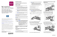
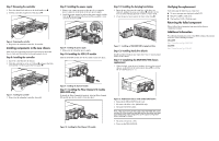
Step 7: Removing the controller 1. Press the thumb latch and rotate the latch handle out 1. 2. Pull the controller straight out of the chassis 2. 2 1 Figure 6: Removing the controller 3. Repeat for the redundant controller, if installed. Installing components in the new chassis After all of the components have been removed from the failed chassis, they must be installed in the replacement chassis. Step 8: Installing the controller 1. Insert the controller into the chassis. 2. Push the controller in as far as it will go 1 and press the latch inward until it is flush against the front panel 2. Step 9: Installing the power supply 1. Remove any connector protector that may be covering the power connector on the front of the new power supply. 2. Install the power supply by pushing the power supply module latch up 1 and pushing in the base until the assembly is fully seated in the enclosure 2. 1 2 Figure 8: Installing the power supply 3. Repeat for the redundant power supply. Step 10: Installing the SCSI I/O module Slide the SCSI I/O module into the bay until it clicks into place. Step 12: Installing the hot-plug hard drives 1. Insert the new drive into the same bay as the drive just removed, sliding it in as far as it will go 1 with the ejector lever is in the full open position to ensure a correct latch. 2. Close the ejector lever against the front of the drive 2. 1 2 Figure 11: Installing an MSA1000/500 hot-plug hard drive Step 13: Installing hard drive blanks Install hard drive blanks in any empty drive bays to ensure proper airflow in the chassis. Step 14: Completing the MSA1000/500 chassis replacement 1. When finished, write the serial number, shown on the original chassis, on the label of the replacement chassis 1, located in the area shown in Figure 12. Verifying the replacement After replacing the failed chassis verify that: ■ No error messages are displayed on the LCD. ■ The power LED is solid green. ■ The heartbeat LED is flashing green. Returning the failed component Please follow the return instructions provided in the new component package. Additional information For additional information, refer to the MSA technical documents web sites at the following locations: MSA1000 http://www.hp.com/go/MSA1000 MAS500 http://www.hp.com/go/MSA500 1 2 Figure 7: Installing the controller 3. Repeat for the redundant controller, if needed. Figure 9: Installing the SCSI I/O module Step 11: Installing the Fibre Channel I/O module (MSA1000 only) To install the Fibre Channel I/O module, slide the Fibre Channel I/O module into the bay until it clicks into place. Figure 10: Installing the Fibre Channel I/O module 1 Figure 12: Replacement chassis serial number label location 2. Reinstall the MSA1000/500 in the rack. 3. Reconnect the fibre cable. (MSA1000 only) 4. Reconnect the SCSI cables. Note: After reconnecting all data cable to the MSA1000/500, make sure that all of the connections are tight and that the cables have been reconnected in the same configuration as the original configuration before replacing the chassis. 5. Reconnect the power cables. 6. Power on the MSA1000/500.
-
 1
1 -
 2
2
 |
 |
