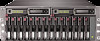
HP StorageWorks Modular Smart Array 1000 HP StorageWorks SCSI I/O Module with - Page 2
Before you begin, Step 1: Removing the module, Verifying the replacement
 |
View all HP StorageWorks Modular Smart Array 1000 manuals
Add to My Manuals
Save this manual to your list of manuals |
Page 2 highlights
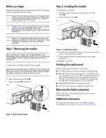
Before you begin Read the following cautions and information before beginning removal and replacement procedures. Caution: Be sure the replacement part is available before removing the failed component. Removing a component impacts cooling within the enclosure. Caution: Parts can be damaged by electrostatic discharge. Use proper anti-static protection. Refer to the documentation that shipped with your system for additional information. Caution: It is important to follow these instructions when replacing components in the MSA. If the procedure is done improperly, it is possible to lose data or damage equipment. Step 1: Removing the module Note: The SCSI I/O module with an integrated EMU is not hot-pluggable. Before replacing the module, all I/O from the servers must be stopped and any attached storage enclosures must be powered off. 1. Disconnect the SCSI cables from the module. Note: Be sure to label the cables so that they can be reattached to the same connector on the replacement module. Failure to reattach the cables to the proper connector results in an error. 2. Press down the release latch 1. 3. Slide the module 2 straight out. 1 Figure 3: Removing the module 2 15080 Step 2: Installing the module To install the new module: 1. Slide the module straight in and make sure it is fully seated 1. 2. Secure the release latch 2. 2 1 15081 Figure 4: Installing the module 3. Reconnect the SCSI cables into the same location noted in step 1 of "Removing the module." 4. Power on any attached storage enclosures and verify connectivity. Installation is complete. Verifying the replacement After replacing the failed switch, be sure that: ■ The EMU indicator on the front panel is blinking green. ■ The fault indicator on the front panel is off. Unread error log messages may cause the LED to remain lit. Be sure all error messages that have been responded to are deleted. Messages can be deleted by simultaneously pressing the left and right navigation buttons on the controller. ■ The SCSI I/O Module power indicator is on. ■ No new error messages are displayed on the LCD. Returning the failed component Please follow the return instructions provided in the new component package. Additional information For additional information, refer to the MSA technical documents web site at http://www.hp.com/go/msa1000.
-
 1
1 -
 2
2
 |
 |
