HP Surestore E Disk Array XP256 Familiarization Guide - Page 25
Operation, Description, Function, ENABLE/DISABLE
 |
View all HP Surestore E Disk Array XP256 manuals
Add to My Manuals
Save this manual to your list of manuals |
Page 25 highlights
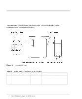
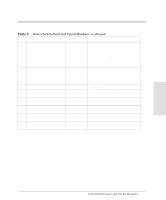
Operation Item Name 1 SUBSYSTEM READY 2 SUBSYSTEM ALARM 3 SUBSYSTEM MESSAGE 4 SUBSYSTEM RESTART 5 REMOTE MAINTENANCE PROCESSING 6 REMOTE MAINTENANCE ENABLE/DISABLE Description Green LED Red LED Amber LED Switch Amber LED 2-Way switch Function Indicates the disk array is ready for operation. Indicates low DC voltage, high DC current, high temperature, or an unrecoverable failure has occurred. Applies to both storage clusters. (Storage clusters consist of two redundant controller halves. Each storage cluster contains all physical and logical elements (for example: power supplies, CHIPs, ACPs, cache, and control storage) needed to sustain processing within the disk array.) Indicates a SIM has been generated. This indicator can be reset only by an HP service representative. Used to unfence a fenced drive path and release the write inhibit command. Applies to both storage clusters. This switch is not used on the open-system model. Applies to both storage clusters. Lit: indicates remote maintenance is possible if authorized and installed. Blinking: indicates a remote maintenance activity is in progress. Enables and disables remote maintenance, if installed. Applies to both storage clusters. 25
-
 1
1 -
2
-
3
-
4
-
5
-
6
-
7
-
8
-
9
-
10
-
11
-
12
-
13
-
14
-
15
-
16
-
17
-
18
-
19
-
 20
20 -
 21
21 -
 22
22 -
 23
23 -
 24
24 -
 25
25 -
 26
26 -
 27
27 -
 28
28 -
 29
29 -
 30
30 -
31
-
32
-
33
-
34
-
35
-
36
-
37
-
38
-
39
-
40
-
41
-
42
-
43
-
44
-
45
-
46
-
47
-
48
-
49
-
50
-
51
-
52
-
53
-
54
-
55
-
56
-
57
-
58
-
59
-
60
-
61
-
62
-
63
-
64
-
65
-
66
-
67
-
68
-
69
-
70
-
71
-
72
 |
 |
