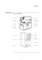
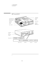
HP Vectra VA 6/xxx HP Vectra VA and XA 6/xxx PCs - Familiarization Guide D4200 - Page 12
Replacing the System Board, Replacing the Power Supply
 |
View all HP Vectra VA 6/xxx manuals
Add to My Manuals
Save this manual to your list of manuals |
Page 12 highlights
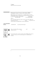
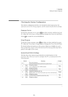
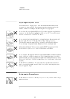
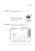
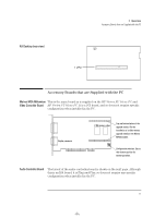
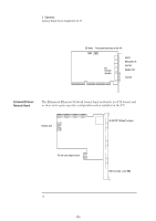
book.bk : 1ch02.fb4 Page 8 Tuesday, June 25, 1996 1:53 PM 2 Operations Replacing the System Board Replacing the System Board After replacing the system board, flash the System ROM with the latest version of the System BIOS. Enter the product identification and serial number, and then reconfigure the PC using the Setup program. Do not plug the cable for the HP Vectra VA control (status) panel into the connector for the XA. Do not plug the cable for the HP Vectra XA control (status) panel into the connector for the VA. XA VA Do not remove the thermal interface material between the processor and the heat-sink. To do so would affect the cooling of the processor. This interface material may stick the processor and heatsink together. Do not attempt to separate them. Manipulate them as a single unit. Always flash the latest version of the System BIOS. You may have been provided with a system board with an old version of the BIOS. Do not reinstall the memory modules haphazardly. There are three memory banks, which can be filled in any order, each comprising a pair of sockets. Different banks can contain memory module pairs of different sizes or types. However, in each bank which is occupied, you must install a pair of identical modules. On the HP Vectra VA 6/xxx PC, always use the specific extraction tool (PLCC IC Extraction, part number 5041-2553) when removing the video memory upgrade chips. Replacing the Power Supply On the HP Vectra VA 6/xxx MT PC, always check the position of the voltage selection switch. 8
-
 1
1 -
2
-
3
-
4
-
5
-
6
-
 7
7 -
 8
8 -
 9
9 -
 10
10 -
 11
11 -
 12
12 -
 13
13 -
 14
14 -
 15
15 -
 16
16 -
 17
17 -
18
-
19
-
20
-
21
-
22
 |
 |
