HP Vectra VE 5/xxx HP Vectra VE 5/xx Series 2 PC - Service Handbook - Page 4
Setup and BIOS, Installing an IDE CD-ROM, System Board Switches - 133 series 3
 |
View all HP Vectra VE 5/xxx manuals
Add to My Manuals
Save this manual to your list of manuals |
Page 4 highlights
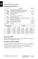
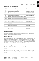
21 HP Vectra VE 5/xx Series 2 PC System Board Switches Switch Function 1-4 - Processor speed, see following table OPEN Enables User and Administrator passwords 5 CLOSED Clears User and Administrator passwords OPEN Normal operation 6 CLOSED Clears CMOS 7 - Processor speed, see following table OPEN Disables secure mode 8 CLOSED Enables secure mode - prevents modification of Setup values and flashing of BIOS OPEN Disables keyboard power-on 9 CLOSED Enables keyboard power-on 10 OPEN Not used Default - OPEN OPEN - OPEN CLOSED OPEN Pentium Processor Frequency 75 MHz 100 MHz 133 MHz 150 MHz 166 MHz 1 Closed Open Open Closed Open 2 Closed Closed Closed Open Closed Switch 3 Open Open Closed Closed Closed 4 Open Open Open Closed Closed 7 Open Closed Closed Closed Closed Setup and BIOS The latest BIOS, the flasher utility program, and the BIOS history can each be obtained from the HP Electronic Services. Installing an IDE CD-ROM It is recommended that the IDE CD-ROM drive be connected to the CD-ROM data cable rather than to the HDD data cable. Connecting the CD-ROM drive to the HDD data cable can reduce the performance of the hard disk drive connected to it. The CD-ROM data cable has a red connector and is marked "CD-ROM" next to the system board connector. 21-4 HP Vectra VE 5/xx Series 2 PC Medium-Profile Desktop Vectras
-
 1
1 -
 2
2 -
 3
3 -
 4
4 -
 5
5 -
 6
6 -
 7
7 -
 8
8
 |
 |
