HP Vectra VT 6/xxx HP Vectra XU 6/xxx and VT 6/xxx PCs - Technical Reference M - Page 40
Addressing System Board Components
 |
View all HP Vectra VT 6/xxx manuals
Add to My Manuals
Save this manual to your list of manuals |
Page 40 highlights
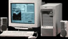
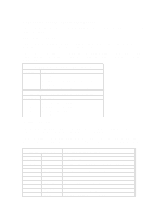
ADDRESSING SYSTEM BOARD COMPONENTS This section provides more details of how the BIOS uses the system board components mentioned in the I/O port list. DMA Channel Controllers Only "I/O-to-memory" and "memory-to-I/O" transfers are allowed."I/O-to-I/O" and "memory-tomemory" transfers are disallowed by the hardware configuration. The system controller supports seven DMA channels, each with a pageregister used to extend the addressing range of the channel to 16 MB. The following table summarizes how the DMA channels are allocated. First DMA controller (used for 8-bit transfers) Channel Function 0 Available 1 SoundBlaster or ECP mode for parallel port 2 Flexible disk I/O 3 ECP mode for parallel port or SoundBlaster Second DMA controller (used for 16-bit transfers) Channel Function 4 Cascade from first DMA controller 5 SoundBlaster or Available 6 Available or SoundBlaster 7 Available Interrupt Controllers The system has two 8259A compatible interrupt controllers. They are arranged as a master interrupt controller and a slave that is cascaded through the master. The following table shows how the master and slave controllers are connected. The Interrupt Requests (IRQ) are numbered sequentially, starting with the master controller, and followed by the slave. IRQ (Interrupt Vector) IRQ0(08h) IRQ1(09h) IRQ2(0Ah) Slave IRQ IRQ8(70h) IRQ9(71h) IRQ10(72h) IRQ11(73h) IRQ12(74h) IRQ13(75h) IRQ14(76h) IRQ15(77h) Interrupt Request Description System Timer Keyboard Controller Cascade connection from INTC2 (Interrupt Controller 2) Real Time Clock Available for accessory board (ISA/PCI) SoundBlaster3, or Available for accessory board (ISA/PCI) Available for accessory board (ISA/PCI) Mouse, or ISA accessory board Co-processor IDE, or ISA accessory board 2nd IDE or ISA/PCI accessory board
-
 1
1 -
2
-
3
-
4
-
5
-
6
-
7
-
8
-
9
-
10
-
11
-
12
-
13
-
14
-
15
-
16
-
17
-
18
-
19
-
20
-
21
-
22
-
23
-
24
-
25
-
26
-
27
-
28
-
29
-
30
-
31
-
32
-
33
-
34
-
 35
35 -
 36
36 -
 37
37 -
 38
38 -
 39
39 -
 40
40 -
 41
41 -
 42
42 -
 43
43 -
 44
44 -
 45
45 -
46
-
47
-
48
-
49
-
50
-
51
 |
 |