| Section |
Page |
| Service Handbook |
1 |
| Service Handbook |
1 |
| Service Handbook |
1 |
| HP Visualize J5000/J7000 Workstations |
1 |
| Edition 1 |
1 |
| HP Part No. A4978-90039 |
1 |
| Printed in USA ��April 1999 |
1 |
| Edition E0499 |
1 |
| Notice |
2 |
| Notice |
2 |
| The information contained in this document is subject to change without notice. |
2 |
| Hewlett-Packard Warranty Statement |
2 |
| Hewlett-Packard Warranty Statement |
2 |
| HP PRODUCT�������������������������������DURATION OF WARRANTY �������������... |
2 |
| 1. HP warrants HP hardware, accessories and supplies against defects in materials and workmanship... |
2 |
| 1. HP warrants HP hardware, accessories and supplies against defects in materials and workmanship... |
2 |
| 1. HP warrants HP hardware, accessories and supplies against defects in materials and workmanship... |
2 |
| 2. HP warrants that HP software will not fail to execute its programming instructions, for the pe... |
2 |
| 2. HP warrants that HP software will not fail to execute its programming instructions, for the pe... |
2 |
| 3. HP does not warrant that the operation of HP products will be uninterrupted or error free. If ... |
2 |
| 3. HP does not warrant that the operation of HP products will be uninterrupted or error free. If ... |
2 |
| 4. HP products may contain remanufactured parts equivalent to new in performance or may have been... |
2 |
| 4. HP products may contain remanufactured parts equivalent to new in performance or may have been... |
2 |
| 5. The warranty period begins on the date of delivery or on the date of installation if installed... |
2 |
| 5. The warranty period begins on the date of delivery or on the date of installation if installed... |
2 |
| 6. Warranty does not apply to defects resulting from (a) improper or inadequate maintenance or ca... |
2 |
| 6. Warranty does not apply to defects resulting from (a) improper or inadequate maintenance or ca... |
2 |
| 7. TO THE EXTENT ALLOWED BY LOCAL LAW, THE ABOVE WARRANTIES ARE EXCLUSIVE AND NO OTHER WARRANTY O... |
2 |
| 7. TO THE EXTENT ALLOWED BY LOCAL LAW, THE ABOVE WARRANTIES ARE EXCLUSIVE AND NO OTHER WARRANTY O... |
2 |
| 8. HP will be liable for damage to tangible property per incident up to the greater of $300,000 o... |
2 |
| 8. HP will be liable for damage to tangible property per incident up to the greater of $300,000 o... |
2 |
| 9. TO THE EXTENT ALLOWED BY LOCAL LAW, THE REMEDIES IN THIS WARRANTY STATEMENT ARE CUSTOMER’S SOL... |
3 |
| 9. TO THE EXTENT ALLOWED BY LOCAL LAW, THE REMEDIES IN THIS WARRANTY STATEMENT ARE CUSTOMER’S SOL... |
3 |
| Restricted Rights Legend |
3 |
| Restricted Rights Legend |
3 |
| Use, duplication, or disclosure by government is subject to restrictions as set forth in subdivis... |
3 |
| © Copyright 1999 |
3 |
| © Copyright 1999 |
3 |
| Hewlett-Packard Company. All Rights Reserved. This document contains proprietary information that... |
3 |
| © Copyright 1980, 1984 |
3 |
| © Copyright 1980, 1984 |
3 |
| AT&T, Inc. |
3 |
| © Copyright 1979, 1980, 1983 |
3 |
| © Copyright 1979, 1980, 1983 |
3 |
| The Regents of the University of California. This software and documentation is based in part on ... |
3 |
| Printing History |
4 |
| Printing History |
4 |
| New editions of this manual incorporate all material updated since the previous edition. Update p... |
4 |
| The manual part number and printing date indicate its current edition. The manual part number cha... |
4 |
| Table of Contents |
5 |
| Table of Figures |
11 |
| Ch 1 Product Information |
15 |
| 1� Product Information |
15 |
| This chapter provides general product information about the HP Visualize J5000 and J7000 workstat... |
15 |
| This chapter provides general product information about the HP Visualize J5000 and J7000 workstat... |
15 |
| Chapter Overview |
16 |
| Chapter Overview |
16 |
| This chapter contains the following main sections: |
16 |
| J5000/J7000 workstation:product description |
16 |
| J5000/J7000 workstation:product description |
16 |
| J5000/J7000 workstation:product description |
16 |
| The HP Visualize J5000 and J7000 workstations are high-performance systems capable of handling th... |
16 |
| J5000/J7000 workstation:differences between J5000 and J7000 |
16 |
| J5000/J7000 workstation:differences between J5000 and J7000 |
16 |
| J5000/J7000 workstation:physical dimensions |
16 |
| J5000/J7000 workstation:physical dimensions |
16 |
| J5000/J7000 workstation:physical dimensions |
16 |
| Physical dimensions of workstation |
16 |
| Dimensions of workstation |
16 |
| Size of workstation, physical |
16 |
| Both workstations use a common chassis, which is 17.5 inches (44.5 cm) high ¥ 13.6 inches (34.5 c... |
16 |
| NOTE For a list of the environmental and electrical requirements for each workstation, see the sp... |
16 |
| NOTE For a list of the environmental and electrical requirements for each workstation, see the sp... |
16 |
| Features of J5000/J7000 workstation |
17 |
| Features of J5000/J7000 workstation |
17 |
| Features of J5000/J7000 workstation |
17 |
| J5000/J7000 workstation:features |
17 |
| The J5000 and J7000 workstations have the following key features. |
17 |
| Microprocessors |
17 |
| Microprocessors |
17 |
| Microprocessors |
17 |
| CPUs |
17 |
| HP-UX: versions supported |
17 |
| HP-UX: versions supported |
17 |
| J5000/J7000 workstation:operating system versions |
17 |
| Operating system, HP-UX:versions supported |
17 |
| J5000/J7000 workstation:user interface |
17 |
| J5000/J7000 workstation:user interface |
17 |
| User interface |
17 |
| HP CDE graphical user interface |
17 |
| Graphical user interface |
17 |
| J5000/J7000 workstation:compatibility with other workstations |
17 |
| J5000/J7000 workstation:compatibility with other workstations |
17 |
| Compatibility with other workstations |
17 |
| J5000/J7000 workstation:memory slots |
17 |
| J5000/J7000 workstation:memory slots |
17 |
| Memory:description of |
17 |
| J5000/J7000 workstation:power supply |
17 |
| J5000/J7000 workstation:power supply |
17 |
| Power supply:description of |
17 |
| J5000/J7000 workstation:internal storage devices |
17 |
| J5000/J7000 workstation:internal storage devices |
17 |
| Internal storage devices:description of |
17 |
| Networking:description of |
17 |
| Networking:description of |
17 |
| J5000/J7000 workstation:networking |
17 |
| Connectors on rear panel:list of |
17 |
| Connectors on rear panel:list of |
17 |
| I/O ports on rear panel:list of |
17 |
| Ports on rear panel:list of |
17 |
| J5000/J7000 workstation:ports |
17 |
| J5000/J7000 workstation:I/O slots |
18 |
| J5000/J7000 workstation:I/O slots |
18 |
| I/O slots:description of |
18 |
| J5000/J7000 workstation:graphics cards supported |
18 |
| J5000/J7000 workstation:graphics cards supported |
18 |
| Graphics cards:list of supported |
18 |
| Cards, I/O: graphics cards supported |
18 |
| • Monitors Supported: |
18 |
| • Standard Keyboard and Mouse: USB (Universal Serial Bus) Series A |
18 |
| J5000/J7000 workstation:front panel components |
18 |
| J5000/J7000 workstation:front panel components |
18 |
| J5000/J7000 workstation:front panel components |
18 |
| Components:front panel |
18 |
| Front panel:components |
18 |
| This section describes the components that are located on the front panel of the J5000 and J7000 ... |
18 |
| Figure 1-1 shows the front panel components with the bezel attached. |
18 |
| Figure�1�1.� Components on the Front Panel with the Bezel Attached |
18 |
| Figure�1�1.� Components on the Front Panel with the Bezel Attached |
18 |
| <GRAPHIC> |
19 |
| Lifting ledge |
19 |
| Lifting ledge |
19 |
| J5000/J7000 workstation:lifting ledge |
19 |
| As noted in Figure 1-1, the hard disk drives are located behind the right-hand door of the front ... |
19 |
| Figure�1�2.� Front Panel with the Bezel Door Open |
19 |
| Figure�1�2.� Front Panel with the Bezel Door Open |
19 |
| <GRAPHIC> |
19 |
| J5000/J7000 workstation:bezel on front panel |
19 |
| Bezel lock, front panel |
19 |
| Bezel, front panel |
19 |
| Front panel:bezel |
19 |
| J5000/J7000 workstation:front panel bezel |
19 |
| Figure 1-3 on the next page shows the front panel of the workstation with the bezel removed. This... |
19 |
| In addition, Figure 1-3 shows the location of the two bezel-detach screw holes on the right-hand ... |
19 |
| Figure�1�3.� Components on the Front Panel with the Bezel Removed |
20 |
| Figure�1�3.� Components on the Front Panel with the Bezel Removed |
20 |
| <GRAPHIC> |
20 |
| • Power switch |
20 |
| • Power switch |
20 |
| • System LCD |
20 |
| • Internal storage devices: |
20 |
| J5000/J7000 workstation:power switch |
20 |
| J5000/J7000 workstation:power switch |
20 |
| J5000/J7000 workstation:power switch |
20 |
| Power switch:description of |
20 |
| Buttons:power |
20 |
| J5000/J7000 workstation:powering off |
20 |
| Powering off the J5000/J7000 |
20 |
| The power switch is located on the left side of the front panel as part of the power switch/LCD a... |
20 |
| NOTE The J5000 and J7000 workstations have a “soft power down” feature that shuts the operating s... |
20 |
| NOTE The J5000 and J7000 workstations have a “soft power down” feature that shuts the operating s... |
20 |
| CAUTION Do |
20 |
| CAUTION Do |
20 |
| J5000/J7000 workstation:LCD |
21 |
| J5000/J7000 workstation:LCD |
21 |
| J5000/J7000 workstation:LCD |
21 |
| LCD:description of |
21 |
| The Liquid Crystal Display (LCD) indicator is located on the left side of the front panel as part... |
21 |
| The following symbols appear in the LCD, representing different system activities. |
21 |
| LCD:symbols |
21 |
| LCD:symbols |
21 |
| LCD:symbols |
21 |
| <GRAPHIC> |
21 |
| J5000/J7000 workstation:internal storage devices |
21 |
| J5000/J7000 workstation:internal storage devices |
21 |
| Internal storage devices:description of |
21 |
| The J5000 and J7000 workstations support the following internal storage devices, which are also l... |
21 |
| • Up to four hot-pluggable, SCA (Single Connector Attach) hard disk drives |
21 |
| • Up to four hot-pluggable, SCA (Single Connector Attach) hard disk drives |
21 |
| • Optionally, one 32X CD drive |
21 |
| • Optionally, either one DDS-3 tape drive, or one 3.5-inch floppy disk drive |
21 |
| The following subsections describe these internal storage devices. |
21 |
| J5000/J7000 workstation:hard disk drives |
21 |
| J5000/J7000 workstation:hard disk drives |
21 |
| J5000/J7000 workstation:hard disk drives |
21 |
| Internal storage devices:hard disk drives |
21 |
| Storage devices:hard disk drives |
21 |
| Drives:hard disk |
21 |
| Hard disk drives:description of |
21 |
| The J5000 and J7000 workstations can support up to four hot-pluggable, SCA (Single Connector Atta... |
21 |
| Hard disk drives:models supported |
21 |
| Hard disk drives:models supported |
21 |
| • 9 GB LVD 10K RPM disk drive (Product Number A4997A) |
21 |
| • 9 GB LVD 10K RPM disk drive (Product Number A4997A) |
21 |
| • 9 GB LVD 10K RPM disk drive (Product Number A4997A) |
21 |
| • 18 GB LVD 10K RPM disk drive (Product Number A4998A) |
21 |
| Hot-plugging hard disk drives |
21 |
| Hot-plugging hard disk drives |
21 |
| Hot-plugging hard disk drives |
21 |
| Hard disk drives:hot-plugging |
21 |
| Internal storage devices:CD drive |
22 |
| Internal storage devices:CD drive |
22 |
| Internal storage devices:CD drive |
22 |
| J5000/J7000 workstation:CD drive |
22 |
| Storage devices:CD drive |
22 |
| Drives:CD |
22 |
| CD drive:description of |
22 |
| As an optional component, the J5000 and J7000 workstations support one 32X CD drive with an ATAPI... |
22 |
| Figure 1-5 shows the operating features of the CD drive, and Table 1-2 describes these features. |
22 |
| Figure�1�5.� CD Drive Features |
22 |
| Figure�1�5.� CD Drive Features |
22 |
| <GRAPHIC> |
22 |
| Table�1�2.� CD Drive Features |
22 |
| <TABLE HEADING> |
22 |
| <TABLE ROW> |
22 |
| Feature |
22 |
| Purpose |
22 |
| Purpose |
22 |
| <TABLE BODY> |
22 |
| <TABLE ROW> |
22 |
| Busy Indicator |
22 |
| Busy Indicator |
22 |
| Lights during a data access operation and blinks during a data transfer. The indicator blinks ini... |
22 |
| Lights during a data access operation and blinks during a data transfer. The indicator blinks ini... |
22 |
| <TABLE ROW> |
22 |
| Emergency Eject Hole |
22 |
| Emergency Eject Hole |
22 |
| Opens the Disk Tray when the end of a paper clip is inserted into it. Used when the workstation d... |
22 |
| <TABLE ROW> |
22 |
| Eject Button |
22 |
| Opens the Disk Tray so that a CD disk may be inserted in it or removed from it. When the drive is... |
22 |
| Opens the Disk Tray so that a CD disk may be inserted in it or removed from it. When the drive is... |
22 |
| <TABLE ROW> |
22 |
| Disk Tray |
22 |
| Holds the CD disk. (Note that this style of CD drive does not use a disk caddy.) |
22 |
| Holds the CD disk. (Note that this style of CD drive does not use a disk caddy.) |
22 |
| J5000/J7000 workstation:DDS-3 tape drive |
23 |
| J5000/J7000 workstation:DDS-3 tape drive |
23 |
| J5000/J7000 workstation:DDS-3 tape drive |
23 |
| Internal storage devices:DDS-3 tape drive |
23 |
| Storage devices:DDS-3 tape drive |
23 |
| Drives:DDS-3 tape |
23 |
| DDS-3 tape drive:description of |
23 |
| The J5000 and J7000 workstations support either one DDS-3 tape drive or one 3.5-inch floppy disk ... |
23 |
| The optional DDS-3 tape drive (Product Number A5011A) is a 3.5-inch, half-height form factor devi... |
23 |
| Figure 1-6 shows the operating features of the DDS-3 tape drive. |
23 |
| Figure�1�6.� DDS-3 Tape Drive Features |
23 |
| Figure�1�6.� DDS-3 Tape Drive Features |
23 |
| <GRAPHIC> |
23 |
| DDS-3 tape drive:LED codes |
23 |
| DDS-3 tape drive:LED codes |
23 |
| DDS-3 tape drive:LED codes |
23 |
| LED codes for DDS-3 tape drive |
23 |
| <GRAPHIC> |
24 |
| J5000/J7000 workstation:floppy disk drive |
24 |
| J5000/J7000 workstation:floppy disk drive |
24 |
| Internal storage devices:floppy disk drive |
24 |
| Storage devices:floppy disk drive |
24 |
| Drives:floppy disk |
24 |
| Floppy disk drive:description of |
24 |
| The J5000 and J7000 workstations support either one DDS-3 tape drive or one 3.5-inch floppy disk ... |
24 |
| The optional floppy disk drive (Product Number A5009A) is a 3.5-inch form factor device with a PC... |
24 |
| Figure 1-8 shows the operating features of the floppy disk drive, and Table 1-3 describes these f... |
24 |
| Figure�1�8.� Floppy Disk Drive Features |
24 |
| Figure�1�8.� Floppy Disk Drive Features |
24 |
| <GRAPHIC> |
24 |
| Table�1�3.� Floppy Disk Drive Features |
24 |
| <TABLE HEADING> |
24 |
| <TABLE ROW> |
24 |
| Feature |
24 |
| Purpose |
24 |
| Purpose |
24 |
| <TABLE BODY> |
24 |
| <TABLE ROW> |
24 |
| Activity LED |
24 |
| Activity LED |
24 |
| Flashes to indicate the floppy disk drive is in use. |
24 |
| Flashes to indicate the floppy disk drive is in use. |
24 |
| <TABLE ROW> |
24 |
| Eject Button |
24 |
| Push to eject a floppy disk from the drive. |
24 |
| Push to eject a floppy disk from the drive. |
24 |
| J5000/J7000 workstation:rear panel components |
25 |
| J5000/J7000 workstation:rear panel components |
25 |
| J5000/J7000 workstation:rear panel components |
25 |
| Components:rear panel |
25 |
| Rear panel components |
25 |
| This section describes the various components located on the rear panel of the J5000 and J7000 wo... |
25 |
| NOTE To maintain FCC/EMI compliance, verify that all cables are fully seated and properly fastened. |
25 |
| NOTE To maintain FCC/EMI compliance, verify that all cables are fully seated and properly fastened. |
25 |
| Figure�1�9.� Components on the Rear Panel |
25 |
| Figure�1�9.� Components on the Rear Panel |
25 |
| <GRAPHIC> |
25 |
| J5000/J7000 workstation:thumbscrews on rear panel |
26 |
| J5000/J7000 workstation:thumbscrews on rear panel |
26 |
| J5000/J7000 workstation:thumbscrews on rear panel |
26 |
| Rear panel components:thumbscrews |
26 |
| Thumbscrews on rear panel |
26 |
| There are two T-15 thumbscrews in the upper corners of the rear panel. Loosening these two screws... |
26 |
| Safety interlock thumbscrew |
26 |
| Safety interlock thumbscrew |
26 |
| Power supply:interlock thumbscrew |
26 |
| Interlock thumbscrew |
26 |
| CAUTION Do |
26 |
| CAUTION Do |
26 |
| J5000/J7000 workstation:connectors on rear panel |
26 |
| J5000/J7000 workstation:connectors on rear panel |
26 |
| J5000/J7000 workstation:connectors on rear panel |
26 |
| This subsection describes the following connectors that are located on the rear panel. Note that ... |
26 |
| • RS-232C Serial connectors |
26 |
| • RS-232C Serial connectors |
26 |
| • LAN 10/100 BaseT RJ45 connector |
26 |
| • USB connectors (for keyboard and mouse only) |
26 |
| • Parallel connector |
26 |
| • SCSI connectors |
26 |
| • Audio connectors |
26 |
| • Power cord connector |
26 |
| Rear panel components:RS-232C serial connectors |
26 |
| Rear panel components:RS-232C serial connectors |
26 |
| Rear panel components:RS-232C serial connectors |
26 |
| RS-232C serial:connectors |
26 |
| Serial:connectors |
26 |
| Connectors on rear panel:RS-232C serial |
26 |
| Ports on rear panel:RS-232C serial |
26 |
| I/O ports on rear panel:RS-232C serial |
26 |
| There are a variety of pointing devices (such as a mouse or trackball) or peripheral devices (inc... |
26 |
| The SIO ports are programmable, allowing functions such as bit rate, character length, parity, an... |
26 |
| Table 1-4 shows the SIO connector pin listings. The serial connectors are 9-pin D-sub connectors.... |
26 |
| <TABLE> |
27 |
| Table�1�4.� Serial I/O Pins |
27 |
| Serial:I/O pins |
27 |
| RS-232C serial:I/O pins |
27 |
| <TABLE HEADING> |
27 |
| <TABLE ROW> |
27 |
| Pin No. |
27 |
| Pin No. |
27 |
| Signal |
27 |
| Description |
27 |
| <TABLE BODY> |
27 |
| <TABLE ROW> |
27 |
| 1 |
27 |
| DCD |
27 |
| Data Carrier Detect |
27 |
| <TABLE ROW> |
27 |
| 2 |
27 |
| RXD |
27 |
| Receive Data |
27 |
| <TABLE ROW> |
27 |
| 3 |
27 |
| TXD |
27 |
| Transmit Data |
27 |
| <TABLE ROW> |
27 |
| 4 |
27 |
| DTR |
27 |
| Data Terminal Ready |
27 |
| <TABLE ROW> |
27 |
| 5 |
27 |
| GND |
27 |
| Ground |
27 |
| <TABLE ROW> |
27 |
| 6 |
27 |
| DSR |
27 |
| Data Set Ready |
27 |
| <TABLE ROW> |
27 |
| 7 |
27 |
| RTS |
27 |
| Request To Send |
27 |
| <TABLE ROW> |
27 |
| 8 |
27 |
| CTS |
27 |
| Clear To Send |
27 |
| <TABLE ROW> |
27 |
| 9 |
27 |
| RI |
27 |
| Ring Indicator |
27 |
| Connectors on rear panel:LAN |
27 |
| Connectors on rear panel:LAN |
27 |
| Connectors on rear panel:LAN |
27 |
| Rear panel components:LAN connector |
27 |
| LAN connector |
27 |
| Networking:connector |
27 |
| RJ45 LAN connector |
27 |
| Ports on rear panel:LAN |
27 |
| I/O ports on rear panel:LAN |
27 |
| Networking:description of |
27 |
| The J5000 and J7000 workstations have one built-in, Ethernet IEEE 802.3, RJ45 Twisted Pair connec... |
27 |
| Rear panel components:USB connectors |
27 |
| Rear panel components:USB connectors |
27 |
| Rear panel components:USB connectors |
27 |
| USB:connectors |
27 |
| Connectors on rear panel:USB |
27 |
| Ports on rear panel:USB |
27 |
| I/O ports on rear panel:USB |
27 |
| The two USB (Universal Serial Bus) Series A connectors on the rear panel of the J5000 and J7000 w... |
27 |
| See the “Keyboard and Mouse” section on |
27 |
| Connectors on rear panel:parallel |
27 |
| Connectors on rear panel:parallel |
27 |
| Connectors on rear panel:parallel |
27 |
| Rear panel components:parallel connector |
27 |
| Parallel connector |
27 |
| Ports on rear panel:parallel |
27 |
| I/O ports on rear panel:parallel |
27 |
| The 25-pin HP Parallel I/O interface uses Centronics interface protocols to support peripheral de... |
27 |
| Rear panel components:SCSI connectors |
28 |
| Rear panel components:SCSI connectors |
28 |
| Rear panel components:SCSI connectors |
28 |
| SCSI:connectors |
28 |
| Connectors on rear panel:SCSI |
28 |
| Ports on rear panel:SCSI |
28 |
| I/O ports on rear panel:SCSI |
28 |
| There are two SCSI connectors on the rear panel: one |
28 |
| Consult the documentation that accompanies each SCSI device for specific information concerning i... |
28 |
| SCSI:mixing NSE and LVD devices on same bus |
28 |
| SCSI:mixing NSE and LVD devices on same bus |
28 |
| SCSI:mixing NSE and LVD devices on same bus |
28 |
| SCSI:terminators |
28 |
| SCSI:terminators |
28 |
| SCSI:terminators |
28 |
| Terminators, SCSI |
28 |
| Connectors on rear panel:audio |
28 |
| Connectors on rear panel:audio |
28 |
| Connectors on rear panel:audio |
28 |
| Rear panel components:audio connectors |
28 |
| Audio:connectors |
28 |
| Ports on rear panel:audio |
28 |
| I/O ports on rear panel:audio |
28 |
| The J5000 and J7000 workstations have audio-input and -output capabilities through external input... |
28 |
| Figure�1�10.� Audio Connectors |
28 |
| Figure�1�10.� Audio Connectors |
28 |
| <GRAPHIC> |
28 |
| <TABLE> |
29 |
| <TABLE> |
29 |
| Table�1�5.� Audio Electrical Specifications |
29 |
| Audio:electrical specifications |
29 |
| Specifications:audio electrical |
29 |
| <TABLE BODY> |
29 |
| <TABLE ROW> |
29 |
| Frequency Response |
29 |
| Frequency Response |
29 |
| 25 Hz to 20 kHz |
29 |
| <TABLE ROW> |
29 |
| Input Sensitivity/Impedance: – Line in – Microphone |
29 |
| 2.0 Vpk/47 Kohm 22 mVpk/1 Kohm |
29 |
| 2.0 Vpk/47 Kohm 22 mVpk/1 Kohm |
29 |
| <TABLE ROW> |
29 |
| Maximum Output Level/Impedance: – Line out – Headphones – Speaker (internal) |
29 |
| 2.8 Vpp/47 Kohm 2.75 Vpp/50 ohm 5.88 Vpp/48 ohm |
29 |
| <TABLE ROW> |
29 |
| Output Impedance: – Line out – Headphones |
29 |
| 619 ohm 118 ohm |
29 |
| Rear panel components:power cord connector |
29 |
| Rear panel components:power cord connector |
29 |
| Rear panel components:power cord connector |
29 |
| Power cord connector |
29 |
| Connectors on rear panel:power cord |
29 |
| Plug the power cord into the power cord connector to provide AC power to the workstation. The pow... |
29 |
| J5000 workstation:power cord connector |
29 |
| J5000 workstation:power cord connector |
29 |
| J7000 workstation:power cord connector |
29 |
| Figure�1�11.� Power Cord Connectors |
29 |
| Figure�1�11.� Power Cord Connectors |
29 |
| <GRAPHIC> |
30 |
| Miscellaneous Components on the Rear Panel |
30 |
| This subsection describes the following, miscellaneous components that are also located on the re... |
30 |
| • Security tab |
30 |
| • Security tab |
30 |
| • TOC button |
30 |
| • I/O slots |
30 |
| J5000/J7000 workstation:security tab |
30 |
| J5000/J7000 workstation:security tab |
30 |
| J5000/J7000 workstation:security tab |
30 |
| Rear panel components:security tab |
30 |
| Security tab |
30 |
| The security tab, which is located at the top of the rear panel, can be used to lock the workstat... |
30 |
| TOC button |
30 |
| TOC button |
30 |
| TOC button |
30 |
| J5000/J7000 workstation:TOC button |
30 |
| Rear panel components:TOC button |
30 |
| Buttons:TOC |
30 |
| The TOC (Transfer Of Control) button interrupts the system. |
30 |
| I/O slots:description of |
30 |
| I/O slots:description of |
30 |
| I/O slots:description of |
30 |
| PCI I/O slots |
30 |
| J5000/J7000 workstation:I/O slots |
30 |
| Rear panel components:I/O slots |
30 |
| The I/O slots located on the rear panel are 64-bit PCI (Peripheral Connect Interface) slots, prov... |
30 |
| 1. Power only – Top slot |
30 |
| 1. Power only – Top slot |
30 |
| 1. Power only – Top slot |
30 |
| 2. PCI-2X (5V, 33 MHz) |
30 |
| 3. PCI-2X (5V, 33 MHz) |
30 |
| 4. PCI-4X (3.3V, 66 MHz) |
30 |
| 5. PCI-2X (5V, 33 MHz) |
30 |
| 6. PCI-2X (5V, 33 MHz) |
30 |
| 7. PCI-4X (3.3V, 66 MHz) |
30 |
| 8. PCI-2X (5V, 33 MHz) – Bottom slot |
30 |
| NOTE Slot 1 is reserved for power only and should |
30 |
| NOTE Slot 1 is reserved for power only and should |
30 |
| For more information about the I/O slots, see the configuration section for |
30 |
| Internal Components |
31 |
| Internal Components |
31 |
| This section describes the internal components of the J5000 and J7000 workstations. The first sub... |
31 |
| For instructions on how to remove the workstation’s top and side panels in order to access these ... |
31 |
| J5000/J7000 workstation:internal components on left side |
31 |
| J5000/J7000 workstation:internal components on left side |
31 |
| J5000/J7000 workstation:internal components on left side |
31 |
| Components:internal on left side |
31 |
| Internal components:left side |
31 |
| J5000/J7000 workstation:differences in internal components |
31 |
| J5000/J7000 workstation:differences in internal components |
31 |
| Figures 1-12 and 1-13 show the internal components located on the left side of the J5000 and the ... |
31 |
| J5000 workstation:internal components on left side |
31 |
| J5000 workstation:internal components on left side |
31 |
| J5000 workstation:internal components on left side |
31 |
| <GRAPHIC> |
32 |
| J7000 workstation:internal components on left side |
32 |
| J7000 workstation:internal components on left side |
32 |
| <GRAPHIC> |
32 |
| J5000/J7000 workstation:system board |
32 |
| J5000/J7000 workstation:system board |
32 |
| System board:description of |
32 |
| The system boards in the J5000 and J7000 contain the PA-8500 microprocessors and memory slots, as... |
32 |
| Over the center wall of the chassis, the system board is attached to the workstation’s I/O board ... |
32 |
| J5000/J7000 workstation:microprocessors |
32 |
| J5000/J7000 workstation:microprocessors |
32 |
| J5000/J7000 workstation:microprocessors |
32 |
| J7000 workstation:microprocessors |
32 |
| J5000 workstation:microprocessors |
32 |
| Microprocessors |
32 |
| CPUs |
32 |
| Turbocoolers, microprocessor |
32 |
| Fans:turbocoolers, microprocessor |
32 |
| You can determine which workstation model it is by counting the microprocessors on the system boa... |
32 |
| J7000 workstation:memory slots |
32 |
| J7000 workstation:memory slots |
32 |
| J7000 workstation:memory slots |
32 |
| J5000/J7000 workstation:memory slots |
32 |
| J5000 workstation:memory slots |
32 |
| Memory:description of |
32 |
| The J5000 and J7000 workstations also differ in the number of memory slots each has on their syst... |
32 |
| For more information about the sizes of memory DIMMs each workstation supports, as well as the DI... |
32 |
| J7000 workstation:DC/DC converter units |
33 |
| J7000 workstation:DC/DC converter units |
33 |
| J7000 workstation:DC/DC converter units |
33 |
| J7000 workstation:air dividers |
33 |
| Air dividers in J7000:description of |
33 |
| DC/DC converter units in J7000:description of |
33 |
| The J7000 has two DC/DC converter units, which provide DC/DC conversion for the workstation, and ... |
33 |
| J5000/J7000 workstation:system board cooling fans |
33 |
| J5000/J7000 workstation:system board cooling fans |
33 |
| J5000/J7000 workstation:system board cooling fans |
33 |
| System board cooling fans:description of |
33 |
| Fans:system board cooling |
33 |
| There are three system board cooling fans in three separate mounting brackets on the front, left ... |
33 |
| J5000/J7000 workstation:internal components on right side |
33 |
| J5000/J7000 workstation:internal components on right side |
33 |
| J5000/J7000 workstation:internal components on right side |
33 |
| Components:internal on right side |
33 |
| Internal components:right side |
33 |
| As you face the J5000 and J7000 workstation, the internal components on the right side of the wor... |
33 |
| Figure 1-14 shows the internal components located on the right side of both the J5000 and J7000 w... |
33 |
| Figure�1�14.� Internal Components on the Right Side of the J5000 and J7000 |
33 |
| Figure�1�14.� Internal Components on the Right Side of the J5000 and J7000 |
33 |
| <GRAPHIC> |
34 |
| J5000/J7000 workstation:power supply |
34 |
| J5000/J7000 workstation:power supply |
34 |
| J7000 workstation:power supply |
34 |
| J5000 workstation:power supply |
34 |
| Power supply:description of |
34 |
| Power supply:fans |
34 |
| Fans:power supply cooling |
34 |
| Although the power supplies in the J5000 and J7000 |
34 |
| The power supply in the J5000 supplies 830 Watts of power to the workstation and is connected to ... |
34 |
| J5000/J7000 workstation:I/O board |
34 |
| J5000/J7000 workstation:I/O board |
34 |
| J5000/J7000 workstation:I/O board |
34 |
| I/O board:description of |
34 |
| The I/O board is mounted on the center wall of the workstation chassis, partially behind the powe... |
34 |
| The I/O board also has 64-bit slots for PCI (Peripheral Connect Interface) cards, providing I/O e... |
34 |
| J5000/J7000 workstation:SCA hard disk interface |
34 |
| J5000/J7000 workstation:SCA hard disk interface |
34 |
| J5000/J7000 workstation:SCA hard disk interface |
34 |
| J5000/J7000 workstation:backplane board |
34 |
| SCA hard disk interface:description of |
34 |
| Backplane board:description of |
34 |
| Hard disk interface, SCA:description of |
34 |
| The SCA (Single Connector Attach) hard disk interface (also known as the backplane board) is moun... |
34 |
| J5000/J7000 workstation:I/O cooling fan |
34 |
| J5000/J7000 workstation:I/O cooling fan |
34 |
| J5000/J7000 workstation:I/O cooling fan |
34 |
| I/O cooling fan:description of |
34 |
| Fans:I/O cooling |
34 |
| The I/O cooling fan is located in the fan/speaker mounting bracket in the bottom of the front, ri... |
34 |
| J5000/J7000 workstation:speaker |
34 |
| J5000/J7000 workstation:speaker |
34 |
| J5000/J7000 workstation:speaker |
34 |
| Speaker:description of |
34 |
| The speaker is mounted within a bracket assembly with the I/O cooling fan. The speaker has 16-bit... |
34 |
| J5000/J7000 workstation:monitors supported |
35 |
| J5000/J7000 workstation:monitors supported |
35 |
| J5000/J7000 workstation:monitors supported |
35 |
| Monitors:supported |
35 |
| The J5000 and J7000 workstations support the following two HP monitors: |
35 |
| • 19-inch (18.3-inch viewable) VGA 1600¥1200 color monitor (Product Number A4575A) |
35 |
| • 19-inch (18.3-inch viewable) VGA 1600¥1200 color monitor (Product Number A4575A) |
35 |
| • 21-inch (19.9-inch viewable) VGA 1600¥1200 color monitor (Product Number A4576A) |
35 |
| J5000/J7000 workstation:keyboard |
35 |
| J5000/J7000 workstation:keyboard |
35 |
| J5000/J7000 workstation:keyboard |
35 |
| J5000/J7000 workstation:mouse |
35 |
| Keyboard supported |
35 |
| Mouse supported |
35 |
| USB:keyboard supported |
35 |
| USB:mouse supported |
35 |
| The standard USB keyboard (Product Number A4983-6 |
35 |
| The standard USB mouse (Product Number A4983-60101) with the workstations is a 3-button pointing ... |
35 |
| J7000 workstation:site preparation guide |
35 |
| J7000 workstation:site preparation guide |
35 |
| J7000 workstation:site preparation guide |
35 |
| Site preparation guide for J7000 |
35 |
| Installation card for J5000/J7000 |
35 |
| For information on: |
35 |
| • Preparing customers’ sites for the delivery and installation of J7000 workstations, refer to th... |
35 |
| • Preparing customers’ sites for the delivery and installation of J7000 workstations, refer to th... |
35 |
| • Preparing customers’ sites for the delivery and installation of J7000 workstations, refer to th... |
35 |
| • Installing J5000 and J7000 workstations, refer to the HP Visualize J5000/J7000 Installation Car... |
35 |
| For a listing of other related documentation for the J5000 and J7000 workstations, see Appendix D... |
35 |
| Ch 2 Configuration |
37 |
| 2� Configuration |
37 |
| This chapter provides details about setting up and changing the system configuration for HP Visua... |
37 |
| This chapter provides details about setting up and changing the system configuration for HP Visua... |
37 |
| Chapter Overview |
38 |
| Chapter Overview |
38 |
| This chapter contains the following main sections: |
38 |
| • Workstation Configurations |
38 |
| • Workstation Configurations |
38 |
| • Field Replaceable Unit (FRU) Configurations |
38 |
| Configuration:workstations |
38 |
| Configuration:workstations |
38 |
| Configuration:workstations |
38 |
| HP Workstations Website |
38 |
| Website, HP Workstations |
38 |
| Workstation configurations |
38 |
| Refer to the HP Workstations Website for a complete list of supported accessories, peripherals, a... |
38 |
| http://hp.unixworkstations.com |
38 |
| Configuration:FRUs |
38 |
| Configuration:FRUs |
38 |
| Configuration:FRUs |
38 |
| FRUs:configuration |
38 |
| This section provides information for setting up or changing the configuration of the Field Repla... |
38 |
| Configuration:internal storage devices |
38 |
| Configuration:internal storage devices |
38 |
| Configuration:internal storage devices |
38 |
| Internal storage devices:configuration |
38 |
| Storage devices:configuration |
38 |
| J5000/J7000 workstation:hard disk drive configuration |
38 |
| J5000/J7000 workstation:hard disk drive configuration |
38 |
| J5000/J7000 workstation:hard disk drive configuration |
38 |
| Configuration:hard disk drive |
38 |
| Hard disk drives:configuration |
38 |
| Hard disk drives:SCSI IDs pre-set |
38 |
| Internal storage devices:hard disk drives |
38 |
| Storage devices:hard disk drives |
38 |
| Drives:hard disk |
38 |
| The SCSI IDs for hard disk drives are hard-wired into the SCA Ultra2 Wide LVD SCSI interfaces in ... |
38 |
| Similarly, no jumpers are installed at the factory, nor is any jumper installation required at th... |
38 |
| Configuration:CD drive |
39 |
| Configuration:CD drive |
39 |
| Configuration:CD drive |
39 |
| CD drive:configuration |
39 |
| J5000/J7000 workstation:CD drive configuration |
39 |
| Internal storage devices:CD drive |
39 |
| Storage devices:CD drive |
39 |
| Drives:CD |
39 |
| The optional CD drive connects to the ATAPI (IDE) interface in the CD drive bay backplane within ... |
39 |
| CD drive:jumper set on C SEL |
39 |
| CD drive:jumper set on C SEL |
39 |
| Figure�2�1.� CD Drive Jumper Setting |
39 |
| Figure�2�1.� CD Drive Jumper Setting |
39 |
| <GRAPHIC> |
39 |
| Configuration:DDS-3 tape drive |
40 |
| Configuration:DDS-3 tape drive |
40 |
| Configuration:DDS-3 tape drive |
40 |
| DDS-3 tape drive:configuration |
40 |
| J5000/J7000 workstation:DDS-3 tape drive configuration |
40 |
| Internal storage devices:DDS-3 tape drive |
40 |
| Storage devices:DDS-3 tape drive |
40 |
| Drives:DDS-3 tape |
40 |
| Figure 2-2 shows the NSE SCSI-2 ID/jumper settings for the optional DDS-3 tape drive. Figure 2-3 ... |
40 |
| See the section titled |
40 |
| DDS-3 tape drive:NSE SCSI-2 ID/jumper settings |
40 |
| DDS-3 tape drive:NSE SCSI-2 ID/jumper settings |
40 |
| DDS-3 tape drive:NSE SCSI-2 ID/jumper settings |
40 |
| <GRAPHIC> |
41 |
| DDS-3 tape drive:Data Compression Operation Mode settings |
41 |
| DDS-3 tape drive:Data Compression Operation Mode settings |
41 |
| <GRAPHIC> |
41 |
| Configuration:floppy disk drive |
41 |
| Configuration:floppy disk drive |
41 |
| Floppy disk drive:configuration |
41 |
| J5000/J7000 workstation:floppy disk drive configuration |
41 |
| Internal storage devices:floppy disk drive |
41 |
| Storage devices:floppy disk drive |
41 |
| Drives:floppy disk |
41 |
| The optional 3.5-inch floppy disk drive requires no ID, switch, or jumper settings. See the secti... |
41 |
| Memory |
41 |
| Memory |
41 |
| Memory:configuration in J5000 |
41 |
| Memory:configuration in J5000 |
41 |
| Memory:configuration in J5000 |
41 |
| Configuration:memory in J5000 |
41 |
| DIMMs:loading order in J5000 |
41 |
| Loading order of DIMMs:in J5000 |
41 |
| J5000 workstation:DIMM loading order |
41 |
| J5000 workstation:memory configuration |
41 |
| The J5000 workstation has eight memory slots, labeled 0 to 7. Memory DIMMs can be installed indiv... |
41 |
| DIMMs should be loaded in the order shown in Figure 2-4, with slot 0 being the first DIMM loaded,... |
41 |
| See the section titled |
42 |
| Figure�2�4.� Memory Loading Order in the J5000 |
42 |
| Figure�2�4.� Memory Loading Order in the J5000 |
42 |
| <GRAPHIC> |
42 |
| Loading order of DIMMs:in J7000 |
42 |
| Loading order of DIMMs:in J7000 |
42 |
| DIMMs:loading order in J7000 |
42 |
| Configuration:memory in J7000 |
42 |
| Memory:configuration in J7000 |
42 |
| J7000 workstation:memory configuration |
42 |
| J7000 workstation:DIMM loading order |
42 |
| The J7000 workstation has sixteen memory slots, labeled 0A, 0B to 7A, 7B. Memory DIMMs |
42 |
| DIMMs should be loaded in the order shown in Figure 2-5, with 0A, 0B being the first pair of DIMM... |
42 |
| See the section titled |
42 |
| Figure�2�5.� Memory Loading Order in the J7000 |
43 |
| Figure�2�5.� Memory Loading Order in the J7000 |
43 |
| <GRAPHIC> |
44 |
| Configuration:I/O cards |
44 |
| Configuration:I/O cards |
44 |
| J5000/J7000 workstation:I/O card configuration |
44 |
| Cards, I/O:configuration |
44 |
| I/O slots:configuring I/O cards |
44 |
| I/O slots:description of |
44 |
| I/O cards:configuring |
44 |
| The I/O slots located on the rear panel of the J5000 and J7000 workstations are 64-bit PCI (Perip... |
44 |
| 1. Power only – Top slot |
44 |
| 1. Power only – Top slot |
44 |
| 1. Power only – Top slot |
44 |
| 2. PCI-2X (5V, 33 MHz) |
44 |
| 3. PCI-2X (5V, 33 MHz) |
44 |
| 4. PCI-4X (3.3V, 66 MHz) |
44 |
| 5. PCI-2X (5V, 33 MHz) |
44 |
| 6. PCI-2X (5V, 33 MHz) |
44 |
| 7. PCI-4X (3.3V, 66 MHz) |
44 |
| 8. PCI-2X (5V, 33 MHz) – Bottom slot |
44 |
| NOTE Slot 1 is reserved for power only and should |
44 |
| NOTE Slot 1 is reserved for power only and should |
44 |
| The following are configuration guidelines for installing I/O cards in the J5000 or J7000: |
44 |
| • Put graphics cards into slot 7 first and slot 4 second. A graphics card can be added to any slo... |
44 |
| • Put graphics cards into slot 7 first and slot 4 second. A graphics card can be added to any slo... |
44 |
| • Put I/O cards into slot 2 first, slot 8 second, slot 3 third, slot 5 fourth, and slot 6 fifth. |
44 |
| • Do |
44 |
| See the section titled |
44 |
| CAUTION The J5000 and J7000 workstations supply about 264 Watts of power to the PCI slots. Do not... |
44 |
| CAUTION The J5000 and J7000 workstations supply about 264 Watts of power to the PCI slots. Do not... |
44 |
| Cards, I/O:installing three FX6 graphics cards simultaneously |
44 |
| Cards, I/O:installing three FX6 graphics cards simultaneously |
44 |
| Cards, I/O:installing three FX6 graphics cards simultaneously |
44 |
| Graphics cards:installing three FX6 simultaneously |
44 |
| I/O slots:installing three FX6 graphics cards simultaneously |
44 |
| Configuration:monitor |
45 |
| Configuration:monitor |
45 |
| Configuration:monitor |
45 |
| Monitors:configuration |
45 |
| J5000/J7000 workstation:monitor configuration |
45 |
| The J5000 and J7000 workstations support the following two HP monitors: |
45 |
| • 19-inch (18.3-inch viewable) VGA 1600¥1200 color monitor (Product Number A4575A) |
45 |
| • 19-inch (18.3-inch viewable) VGA 1600¥1200 color monitor (Product Number A4575A) |
45 |
| • 21-inch (19.9-inch viewable) VGA 1600¥1200 color monitor (Product Number A4576A) |
45 |
| The monitor type does not have to be changed on these workstations since the workstations are set... |
45 |
| NOTE Unsupported monitors may “lock up” if they cannot sync to a scan rate. |
45 |
| NOTE Unsupported monitors may “lock up” if they cannot sync to a scan rate. |
45 |
| Ch 3 Troubleshooting |
47 |
| FRUs:troubleshooting |
47 |
| FRUs:troubleshooting |
47 |
| J5000/J7000 workstation:troubleshooting |
47 |
| This chapter provides information about isolating a failing component, known as a Field Replaceab... |
47 |
| This chapter provides information about isolating a failing component, known as a Field Replaceab... |
47 |
| Chapter Overview |
48 |
| Chapter Overview |
48 |
| This chapter contains the following main sections: |
48 |
| Troubleshooting:introduction to |
48 |
| Troubleshooting:introduction to |
48 |
| Troubleshooting:introduction to |
48 |
| To troubleshoot HP Visualize J5000 and J7000 workstations, you must be familiar with the HP-UX op... |
48 |
| First note any error or status messages, and then run the power-up boot ROM diagnostics, known as... |
48 |
| For a complete description of using ISL diagnostics and using the Support Tools Manager, see the ... |
48 |
| Flowcharts for Troubleshooting |
48 |
| Flowcharts for Troubleshooting |
48 |
| The following four figures contain troubleshooting flowcharts you can follow to isolate a failing... |
48 |
| Flowcharts for troubleshooting |
49 |
| Flowcharts for troubleshooting |
49 |
| Flowcharts for troubleshooting |
49 |
| J5000/J7000 workstation:flowcharts for troubleshooting |
49 |
| Troubleshooting:flowcharts |
49 |
| Main troubleshooting flowchart |
49 |
| <GRAPHIC> |
50 |
| Console troubleshooting flowchart |
50 |
| Console troubleshooting flowchart |
50 |
| <GRAPHIC> |
51 |
| Bootable device troubleshooting flowchart |
51 |
| Bootable device troubleshooting flowchart |
51 |
| <GRAPHIC> |
52 |
| HP-UX:troubleshooting flowchart |
52 |
| HP-UX:troubleshooting flowchart |
52 |
| Operating system, HP-UX:troubleshooting flowchart |
52 |
| <GRAPHIC> |
53 |
| J5000/J7000 workstation:boot failure |
53 |
| J5000/J7000 workstation:boot failure |
53 |
| Troubleshooting:boot failure |
53 |
| Boot:failure, troubleshooting |
53 |
| Problems:boot failure |
53 |
| Failures:boot |
53 |
| To start this workstation from an operating system stored on a device different from the usual bo... |
53 |
| • To boot from a known device containing a bootable operating system, type the following at the p... |
53 |
| • To boot from a known device containing a bootable operating system, type the following at the p... |
53 |
| • To interact with the Initial System Loader (ISL) before booting the workstation, type the follo... |
53 |
| • To find the location of the bootable operating systems on the various media in the file system,... |
53 |
| J5000/J7000 workstation:bootable media |
54 |
| J5000/J7000 workstation:bootable media |
54 |
| J5000/J7000 workstation:bootable media |
54 |
| Troubleshooting:bootable media |
54 |
| Bootable media |
54 |
| To list all devices that contain bootable media, go to the Main Menu of the Boot Console Handler,... |
54 |
| Main Menu: Enter command > search ipl [Enter] |
54 |
| The |
54 |
| • To temporarily suspend the search, press |
54 |
| • To temporarily suspend the search, press |
54 |
| • To continue the search, press |
54 |
| • To halt the search, press any other key. |
54 |
| These flow-control commands do not work with a bitmapped display, but such a display can show mor... |
54 |
| To search for devices of just one type that actually contain bootable media, go to the Main Menu ... |
54 |
| Main Menu: Enter command > search ipl device_type [Enter] |
54 |
| where |
54 |
| Troubleshooting:stable storage |
54 |
| Troubleshooting:stable storage |
54 |
| Troubleshooting:stable storage |
54 |
| J5000/J7000 workstation:stable storage |
54 |
| Stable storage |
54 |
| Stable Storage is non-volatile memory associated with the PA-RISC processor module. Stable Storag... |
54 |
| J5000/J7000 workstation:boot command notations |
54 |
| J5000/J7000 workstation:boot command notations |
54 |
| J5000/J7000 workstation:boot command notations |
54 |
| Troubleshooting:boot command notations |
54 |
| Boot:command notations |
54 |
| The |
54 |
| • Mnemonic |
54 |
| • Mnemonic |
54 |
| • Path number |
54 |
| Type |
54 |
| Here are examples of mnemonic notation: |
54 |
| • boot |
54 |
| • boot |
54 |
| • boot |
54 |
| • boot |
54 |
| • boot |
54 |
| Here is an example of path number notation: |
55 |
| • boot p1 [Enter] |
55 |
| • boot p1 [Enter] |
55 |
| • boot p1 [Enter] |
55 |
| J5000/J7000 workstation:boot paths supported |
55 |
| J5000/J7000 workstation:boot paths supported |
55 |
| J5000/J7000 workstation:boot paths supported |
55 |
| Troubleshooting:boot paths |
55 |
| Boot:paths supported |
55 |
| SCSI devices are bootable when connected to any SCSI port on the system. Diskless workstations ca... |
55 |
| J5000/J7000 workstation:ISL environment |
55 |
| J5000/J7000 workstation:ISL environment |
55 |
| J5000/J7000 workstation:ISL environment |
55 |
| Troubleshooting:ISL environment |
55 |
| ISL environment |
55 |
| The ISL environment provides the means to load the operating system (HP-UX) environment. The ISL ... |
55 |
| The ISL program is the first program loaded into main memory from an external media (LAN, disk, o... |
55 |
| The ISL environment provides the following capabilities: |
55 |
| • Execute user-entered commands to modify boot device paths and boot options in stable storage. |
55 |
| • Execute user-entered commands to modify boot device paths and boot options in stable storage. |
55 |
| • Run off-line diagnostic programs and utilities. |
55 |
| • Provide automatic booting of the HP-UX operating system after power-on or reset. |
55 |
| J5000/J7000 workstation:LCD-indicated conditions |
56 |
| J5000/J7000 workstation:LCD-indicated conditions |
56 |
| J5000/J7000 workstation:LCD-indicated conditions |
56 |
| Troubleshooting:LCD-indicated conditions |
56 |
| LCD-indicated conditions, troubleshooting |
56 |
| Chassis codes |
56 |
| LCD:chassis codes |
56 |
| This workstation uses a 2-line LCD, with up to 16-characters per line, to display firmware/operat... |
56 |
| XXX �YYYY: �ZZZZZZ������������(Line 1) |
56 |
| XXX �YYYY: �ZZZZZZ������������(Line 1) |
56 |
| XXX �YYYY: �ZZZZZZ������������(Line 1) |
56 |
| AAAAAAAAAAAAAAAA������(Line 2) |
56 |
| Where: |
56 |
| XXX – represents a 3-character Ostat |
56 |
| XXX – represents a 3-character Ostat |
56 |
| YYYY – represents a 4-digit hex code identifying the code module being executed |
56 |
| ZZZZZZ – represents a 6-digit FRU descriptor |
56 |
| AAAAAAAAAAAAAAAA – represents text (up to 16 characters) relating a diagnostic message |
56 |
| Ostat code meanings |
56 |
| Ostat code meanings |
56 |
| • FLT |
56 |
| • FLT |
56 |
| • FLT |
56 |
| • TST |
56 |
| • TST |
56 |
| • INI |
56 |
| • INI |
56 |
| • SHU |
56 |
| • SHU |
56 |
| • WRN |
56 |
| • WRN |
56 |
| • RUN |
56 |
| • RUN |
56 |
| Selftest Failures |
56 |
| Selftest Failures |
56 |
| Failures:selftest |
56 |
| Failures:selftest |
56 |
| J5000/J7000 workstation:selftest failures |
56 |
| Selftest failures |
56 |
| Tests:selftest |
56 |
| Problems:selftest failures |
56 |
| 1. In Table 3-1 starting on the next page, find the chassis code listed on the LCD. |
56 |
| 1. In Table 3-1 starting on the next page, find the chassis code listed on the LCD. |
56 |
| 2. In the Boot Console Handler, use the Service Menu’s |
56 |
| The FRU column in Table 3-1 shows messages printed on the LCD that refer to system FRUs. All code... |
56 |
| Memory:failures |
56 |
| Memory:failures |
56 |
| Memory:failures |
56 |
| J5000/J7000 workstation:memory failures |
56 |
| Troubleshooting:memory failures |
56 |
| Problems:memory |
56 |
| Failures:memory |
56 |
| PDC feature |
56 |
| Memory Page Deallocation (PDC) feature |
56 |
| The J5000 and J7000 workstations require special Memory Page Deallocation to be implemented. This... |
56 |
| HP-UX 10.x uses this information to map out failing memory areas and continue normal operation. Y... |
56 |
| J5000/J7000 workstation:chassis codes |
57 |
| J5000/J7000 workstation:chassis codes |
57 |
| J5000/J7000 workstation:chassis codes |
57 |
| Troubleshooting:chassis codes |
57 |
| Chassis codes |
57 |
| Failures:chassis codes |
57 |
| Problems:chassis codes |
57 |
| LCD:chassis codes |
57 |
| Table 3-1 lists all of the chassis codes for the J5000 and J7000 workstations. |
57 |
| <TABLE> |
57 |
| <TABLE> |
57 |
| Table�3�1.� Chassis Codes for J5000 and J7000 Workstations |
57 |
| <TABLE HEADING> |
57 |
| <TABLE ROW> |
57 |
| Ostat |
57 |
| Ostat |
57 |
| Code |
57 |
| FRU |
57 |
| Message |
57 |
| Description |
57 |
| Description |
57 |
| <TABLE BODY> |
57 |
| <TABLE ROW> |
57 |
| FLT |
57 |
| 1n01 |
57 |
| SYS BD |
57 |
| SYS BD |
57 |
| HPMC occurred |
57 |
| HPMC occurred |
57 |
| CPU n detected an unexpected HPMC. |
57 |
| CPU n detected an unexpected HPMC. |
57 |
| <TABLE ROW> |
57 |
| FLT |
57 |
| 1n02 |
57 |
| SYS BD |
57 |
| SYS BD |
57 |
| powerfail intrpt |
57 |
| powerfail intrpt |
57 |
| CPU n detected an unexpected power fail interrupt. |
57 |
| CPU n detected an unexpected power fail interrupt. |
57 |
| <TABLE ROW> |
57 |
| FLT |
57 |
| 1n03 |
57 |
| SYS BD |
57 |
| SYS BD |
57 |
| recvry cntr trap |
57 |
| recvry cntr trap |
57 |
| CPU n detected an unexpected recovery counter trap. |
57 |
| CPU n detected an unexpected recovery counter trap. |
57 |
| <TABLE ROW> |
57 |
| FLT |
57 |
| 1n04 |
57 |
| SYS BD |
57 |
| SYS BD |
57 |
| external intrrpt |
57 |
| external intrrpt |
57 |
| CPU n detected an unexpected external interrupt. |
57 |
| CPU n detected an unexpected external interrupt. |
57 |
| <TABLE ROW> |
57 |
| FLT |
57 |
| 1n05 |
57 |
| SYS BD |
57 |
| SYS BD |
57 |
| LPMC occurred |
57 |
| LPMC occurred |
57 |
| CPU n detected an unexpected LPMC. |
57 |
| CPU n detected an unexpected LPMC. |
57 |
| <TABLE ROW> |
57 |
| FLT |
57 |
| 1n06 |
57 |
| SYS BD |
57 |
| SYS BD |
57 |
| ITLB mis/Ipg flt |
57 |
| ITLB mis/Ipg flt |
57 |
| CPU n detected an unexpected ITLB miss or instruction page fault. |
57 |
| CPU n detected an unexpected ITLB miss or instruction page fault. |
57 |
| <TABLE ROW> |
57 |
| FLT |
57 |
| 1n07 |
57 |
| SYS BD |
57 |
| SYS BD |
57 |
| I mem prot trap |
57 |
| I mem prot trap |
57 |
| CPU n detected an unexpected instruction memory protection trap. |
57 |
| CPU n detected an unexpected instruction memory protection trap. |
57 |
| <TABLE ROW> |
57 |
| FLT |
57 |
| 1n08 |
57 |
| SYS BD |
57 |
| SYS BD |
57 |
| illegal inst trp |
57 |
| illegal inst trp |
57 |
| CPU n detected an unexpected illegal instruction trap. |
57 |
| CPU n detected an unexpected illegal instruction trap. |
57 |
| <TABLE ROW> |
57 |
| FLT |
57 |
| 1n09 |
57 |
| SYS BD |
57 |
| SYS BD |
57 |
| break instr trap |
57 |
| break instr trap |
57 |
| CPU n detected an unexpected break instruction trap. |
57 |
| CPU n detected an unexpected break instruction trap. |
57 |
| <TABLE ROW> |
57 |
| FLT |
57 |
| 1n0A |
57 |
| SYS BD |
57 |
| SYS BD |
57 |
| privilgd op trap |
57 |
| privilgd op trap |
57 |
| CPU n detected an unexpected privileged operation trap. |
57 |
| CPU n detected an unexpected privileged operation trap. |
57 |
| <TABLE ROW> |
57 |
| FLT |
57 |
| 1n0B |
57 |
| SYS BD |
57 |
| SYS BD |
57 |
| privlgd reg trap |
57 |
| privlgd reg trap |
57 |
| CPU n detected an unexpected privileged register trap. |
57 |
| CPU n detected an unexpected privileged register trap. |
57 |
| <TABLE ROW> |
57 |
| FLT |
57 |
| 1n0C |
57 |
| SYS BD |
57 |
| SYS BD |
57 |
| overflow trap |
57 |
| overflow trap |
57 |
| CPU n detected an unexpected overflow trap. |
57 |
| CPU n detected an unexpected overflow trap. |
57 |
| <TABLE ROW> |
57 |
| FLT |
57 |
| 1n0D |
57 |
| SYS BD |
57 |
| SYS BD |
57 |
| conditional trap |
57 |
| conditional trap |
57 |
| CPU n detected an unexpected conditional trap. |
57 |
| CPU n detected an unexpected conditional trap. |
57 |
| <TABLE ROW> |
57 |
| FLT |
57 |
| 1n0E |
57 |
| SYS BD |
57 |
| SYS BD |
57 |
| assist exep trap |
57 |
| assist exep trap |
57 |
| CPU n detected an unexpected assist exception trap. |
57 |
| CPU n detected an unexpected assist exception trap. |
57 |
| <TABLE ROW> |
57 |
| FLT |
57 |
| 1n0F |
57 |
| SYS BD |
57 |
| SYS BD |
57 |
| DTLB mis/Dpg flt |
57 |
| DTLB mis/Dpg flt |
57 |
| CPU n detected an unexpected DTLB miss or data page fault. |
57 |
| CPU n detected an unexpected DTLB miss or data page fault. |
57 |
| <TABLE ROW> |
57 |
| FLT |
57 |
| 1n10 |
57 |
| SYS BD |
57 |
| SYS BD |
57 |
| non-acc ITLB mis |
57 |
| non-acc ITLB mis |
57 |
| CPU n detected an unexpected non-access ITLB miss fault. |
57 |
| CPU n detected an unexpected non-access ITLB miss fault. |
57 |
| <TABLE ROW> |
57 |
| FLT |
57 |
| 1n11 |
57 |
| SYS BD |
57 |
| SYS BD |
57 |
| non-acc DTLB mis |
57 |
| non-acc DTLB mis |
57 |
| CPU n detected an unexpected non-access DTLB miss or data page fault. |
57 |
| CPU n detected an unexpected non-access DTLB miss or data page fault. |
57 |
| <TABLE ROW> |
58 |
| FLT |
58 |
| 1n12 |
58 |
| SYS BD |
58 |
| SYS BD |
58 |
| data mem prot tr |
58 |
| data mem prot tr |
58 |
| CPU n detected an unexpected data memory protection trap. |
58 |
| CPU n detected an unexpected data memory protection trap. |
58 |
| <TABLE ROW> |
58 |
| FLT |
58 |
| 1n13 |
58 |
| SYS BD |
58 |
| SYS BD |
58 |
| data mem brk trp |
58 |
| data mem brk trp |
58 |
| CPU n detected an unexpected data memory break trap. |
58 |
| CPU n detected an unexpected data memory break trap. |
58 |
| <TABLE ROW> |
58 |
| FLT |
58 |
| 1n14 |
58 |
| SYS BD |
58 |
| SYS BD |
58 |
| TLB dirty bit tr |
58 |
| TLB dirty bit tr |
58 |
| CPU n detected an unexpected TLB dirty bit trap. |
58 |
| CPU n detected an unexpected TLB dirty bit trap. |
58 |
| <TABLE ROW> |
58 |
| FLT |
58 |
| 1n15 |
58 |
| SYS BD |
58 |
| SYS BD |
58 |
| page refrnce trp |
58 |
| page refrnce trp |
58 |
| CPU n detected an unexpected page reference trap. |
58 |
| CPU n detected an unexpected page reference trap. |
58 |
| <TABLE ROW> |
58 |
| FLT |
58 |
| 1n16 |
58 |
| SYS BD |
58 |
| SYS BD |
58 |
| assist emul trap |
58 |
| assist emul trap |
58 |
| CPU n detected an unexpected assist emulation trap. |
58 |
| CPU n detected an unexpected assist emulation trap. |
58 |
| <TABLE ROW> |
58 |
| FLT |
58 |
| 1n17 |
58 |
| SYS BD |
58 |
| SYS BD |
58 |
| hi-priv xfer trp |
58 |
| hi-priv xfer trp |
58 |
| CPU n detected an unexpected higher-privilege transfer trap. |
58 |
| CPU n detected an unexpected higher-privilege transfer trap. |
58 |
| <TABLE ROW> |
58 |
| FLT |
58 |
| 1n18 |
58 |
| SYS BD |
58 |
| SYS BD |
58 |
| lo-priv xfer trp |
58 |
| lo-priv xfer trp |
58 |
| CPU n detected an unexpected lower-privilege transfer trap. |
58 |
| CPU n detected an unexpected lower-privilege transfer trap. |
58 |
| <TABLE ROW> |
58 |
| FLT |
58 |
| 1n19 |
58 |
| SYS BD |
58 |
| SYS BD |
58 |
| taken branch trp |
58 |
| taken branch trp |
58 |
| CPU n detected an unexpected taken-branch trap. |
58 |
| CPU n detected an unexpected taken-branch trap. |
58 |
| <TABLE ROW> |
58 |
| FLT |
58 |
| 1n1A |
58 |
| SYS BD |
58 |
| SYS BD |
58 |
| data mem acc rts |
58 |
| data mem acc rts |
58 |
| CPU n detected an unexpected data memory access rights trap. |
58 |
| CPU n detected an unexpected data memory access rights trap. |
58 |
| <TABLE ROW> |
58 |
| FLT |
58 |
| 1n1B |
58 |
| SYS BD |
58 |
| SYS BD |
58 |
| data mem prot ID |
58 |
| data mem prot ID |
58 |
| CPU n detected an unexpected data memory protection ID trap. |
58 |
| CPU n detected an unexpected data memory protection ID trap. |
58 |
| <TABLE ROW> |
58 |
| FLT |
58 |
| 1n1C |
58 |
| SYS BD |
58 |
| SYS BD |
58 |
| unalign data ref |
58 |
| unalign data ref |
58 |
| CPU n detected an unexpected unaligned data reference trap. |
58 |
| CPU n detected an unexpected unaligned data reference trap. |
58 |
| <TABLE ROW> |
58 |
| FLT |
58 |
| 1n1D |
58 |
| SYS BD |
58 |
| SYS BD |
58 |
| perf mon intrrpt |
58 |
| perf mon intrrpt |
58 |
| CPU n detected an unexpected performance monitor interrupt. |
58 |
| CPU n detected an unexpected performance monitor interrupt. |
58 |
| <TABLE ROW> |
58 |
| TST |
58 |
| 1n20 |
58 |
| 1n20 |
58 |
| SYS BD |
58 |
| SYS BD |
58 |
| CPUn basic test |
58 |
| CPU |
58 |
| CPU n is starting its basic operations self-test. |
58 |
| CPU n is starting its basic operations self-test. |
58 |
| <TABLE ROW> |
58 |
| TST |
58 |
| TST |
58 |
| 1n21 |
58 |
| 1n21 |
58 |
| SYS BD |
58 |
| SYS BD |
58 |
| CPUn alu test |
58 |
| CPU |
58 |
| CPU n is starting its arithmetic and logical unit self-test. |
58 |
| CPU n is starting its arithmetic and logical unit self-test. |
58 |
| <TABLE ROW> |
58 |
| TST |
58 |
| TST |
58 |
| 1n22 |
58 |
| 1n22 |
58 |
| SYS BD |
58 |
| SYS BD |
58 |
| CPUn branch test |
58 |
| CPU |
58 |
| CPU n is starting its branch instruction self-test. |
58 |
| CPU n is starting its branch instruction self-test. |
58 |
| <TABLE ROW> |
58 |
| TST |
58 |
| 1n23 |
58 |
| 1n23 |
58 |
| SYS BD |
58 |
| SYS BD |
58 |
| CPUn arith cond |
58 |
| CPU |
58 |
| CPU n is starting its arthimetic condition self-test. |
58 |
| CPU n is starting its arthimetic condition self-test. |
58 |
| <TABLE ROW> |
58 |
| TST |
58 |
| TST |
58 |
| 1n24 |
58 |
| 1n24 |
58 |
| SYS BD |
58 |
| SYS BD |
58 |
| CPUn bit opers |
58 |
| CPU |
58 |
| CPU n is starting its bit operation instruction self-test. |
58 |
| CPU n is starting its bit operation instruction self-test. |
58 |
| <TABLE ROW> |
58 |
| TST |
58 |
| 1n25 |
58 |
| 1n25 |
58 |
| SYS BD |
58 |
| SYS BD |
58 |
| CPUn cntrl regs |
58 |
| CPU |
58 |
| CPU n is starting its control register self-test. |
58 |
| CPU n is starting its control register self-test. |
58 |
| <TABLE ROW> |
59 |
| TST |
59 |
| TST |
59 |
| 1n26 |
59 |
| 1n26 |
59 |
| SYS BD |
59 |
| SYS BD |
59 |
| CPUn ext intrpt |
59 |
| CPU |
59 |
| CPU n is starting its external interrupt self-test. |
59 |
| CPU n is starting its external interrupt self-test. |
59 |
| <TABLE ROW> |
59 |
| TST |
59 |
| 1n27 |
59 |
| 1n27 |
59 |
| SYS BD |
59 |
| SYS BD |
59 |
| CPUn itimer test |
59 |
| CPU |
59 |
| CPU n is starting its interval timer self-test. |
59 |
| CPU n is starting its interval timer self-test. |
59 |
| <TABLE ROW> |
59 |
| TST |
59 |
| 1n28 |
59 |
| 1n28 |
59 |
| SYS BD |
59 |
| SYS BD |
59 |
| CPUn multi-media |
59 |
| CPU |
59 |
| CPU n is starting its multi-media instructions self-test. |
59 |
| CPU n is starting its multi-media instructions self-test. |
59 |
| <TABLE ROW> |
59 |
| TST |
59 |
| TST |
59 |
| 1n29 |
59 |
| 1n29 |
59 |
| SYS BD |
59 |
| SYS BD |
59 |
| CPUn shadow reg |
59 |
| CPU |
59 |
| CPU n is starting its shadow register self-test. |
59 |
| CPU n is starting its shadow register self-test. |
59 |
| <TABLE ROW> |
59 |
| TST |
59 |
| TST |
59 |
| 1n2A |
59 |
| 1n2A |
59 |
| SYS BD |
59 |
| SYS BD |
59 |
| CPUn diagnse reg |
59 |
| CPU |
59 |
| CPU n is starting its diagnose register self-test. |
59 |
| CPU n is starting its diagnose register self-test. |
59 |
| <TABLE ROW> |
59 |
| TST |
59 |
| TST |
59 |
| 1n2B |
59 |
| 1n2B |
59 |
| SYS BD |
59 |
| SYS BD |
59 |
| CPUn rdr test |
59 |
| CPU |
59 |
| CPU n is starting its remote diagnose register self-test. |
59 |
| CPU n is starting its remote diagnose register self-test. |
59 |
| <TABLE ROW> |
59 |
| TST |
59 |
| TST |
59 |
| 1n2C |
59 |
| 1n2C |
59 |
| SYS BD |
59 |
| SYS BD |
59 |
| CPUn bypass test |
59 |
| CPU |
59 |
| CPU n is starting its integer bypass operation self-test. |
59 |
| CPU n is starting its integer bypass operation self-test. |
59 |
| <TABLE ROW> |
59 |
| TST |
59 |
| 1n30 |
59 |
| 1n30 |
59 |
| SYS BD |
59 |
| SYS BD |
59 |
| CPUn start est |
59 |
| CPU |
59 |
| CPU n is starting its early (pre-memory) self-tests. |
59 |
| CPU n is starting its early (pre-memory) self-tests. |
59 |
| <TABLE ROW> |
59 |
| WRN |
59 |
| WRN |
59 |
| 1n31 |
59 |
| SYS BD |
59 |
| SYS BD |
59 |
| CPUn skip est |
59 |
| CPU n is bypassing its early self-tests to save time. |
59 |
| CPU n is bypassing its early self-tests to save time. |
59 |
| <TABLE ROW> |
59 |
| FLT |
59 |
| FLT |
59 |
| 1n32 |
59 |
| SYS BD |
59 |
| SYS BD |
59 |
| CPUn bad tst mod |
59 |
| CPU |
59 |
| CPU n detected an unsupported system mode. |
59 |
| CPU n detected an unsupported system mode. |
59 |
| <TABLE ROW> |
59 |
| INI |
59 |
| INI |
59 |
| 1n3C |
59 |
| 1n3C |
59 |
| SYS BD |
59 |
| SYS BD |
59 |
| CPUn initialize |
59 |
| CPU |
59 |
| CPU n is initializing after self-tests. |
59 |
| CPU n is initializing after self-tests. |
59 |
| <TABLE ROW> |
59 |
| TST |
59 |
| TST |
59 |
| 1n3E |
59 |
| SYS BD |
59 |
| SYS BD |
59 |
| CPUn exit er tst |
59 |
| CPU n finished its early self-tests. |
59 |
| CPU n finished its early self-tests. |
59 |
| <TABLE ROW> |
59 |
| TST |
59 |
| TST |
59 |
| 1nA0 |
59 |
| 1nA0 |
59 |
| SYS BD |
59 |
| SYS BD |
59 |
| CPUn fpu tests |
59 |
| CPU |
59 |
| CPU n is starting its floating-point unit self-tests. |
59 |
| CPU n is starting its floating-point unit self-tests. |
59 |
| <TABLE ROW> |
59 |
| TST |
59 |
| TST |
59 |
| 1nA1 |
59 |
| 1nA1 |
59 |
| SYS BD |
59 |
| SYS BD |
59 |
| CPUn fpu reg tst |
59 |
| CPU |
59 |
| CPU n is starting its floating-point register self-test. |
59 |
| CPU n is starting its floating-point register self-test. |
59 |
| <TABLE ROW> |
59 |
| TST |
59 |
| 1nA2 |
59 |
| 1nA2 |
59 |
| SYS BD |
59 |
| SYS BD |
59 |
| CPUn fpu inst |
59 |
| CPU |
59 |
| CPU n is starting its floating-point instruction self-test. |
59 |
| CPU n is starting its floating-point instruction self-test. |
59 |
| <TABLE ROW> |
59 |
| TST |
59 |
| TST |
59 |
| 1nA3 |
59 |
| 1nA3 |
59 |
| SYS BD |
59 |
| SYS BD |
59 |
| CPUn fpu traps |
59 |
| CPU |
59 |
| CPU n is starting its floating-point trap self-test. |
59 |
| CPU n is starting its floating-point trap self-test. |
59 |
| <TABLE ROW> |
59 |
| TST |
59 |
| TST |
59 |
| 1nA4 |
59 |
| 1nA4 |
59 |
| SYS BD |
59 |
| SYS BD |
59 |
| CPUn fpu misc |
59 |
| CPU |
59 |
| CPU n is starting its floating-point miscellaneous operations self-test. |
59 |
| CPU n is starting its floating-point miscellaneous operations self-test. |
59 |
| <TABLE ROW> |
59 |
| TST |
59 |
| TST |
59 |
| 1nA5 |
59 |
| 1nA5 |
59 |
| SYS BD |
59 |
| SYS BD |
59 |
| CPUn fpu bypass |
59 |
| CPU |
59 |
| CPU n is starting its floating-point bypassing self-test. |
59 |
| CPU n is starting its floating-point bypassing self-test. |
59 |
| <TABLE ROW> |
59 |
| TST |
59 |
| TST |
59 |
| 1nB1 |
59 |
| 1nB1 |
59 |
| SYS BD |
59 |
| SYS BD |
59 |
| CPUn TLB RAM tst |
59 |
| CPU |
59 |
| CPU n is starting its TLB register self-test. |
59 |
| CPU n is starting its TLB register self-test. |
59 |
| <TABLE ROW> |
60 |
| TST |
60 |
| TST |
60 |
| 1nB2 |
60 |
| 1nB2 |
60 |
| SYS BD |
60 |
| SYS BD |
60 |
| CPUn TLB trans |
60 |
| CPU |
60 |
| CPU n is starting its TLB translation self-test. |
60 |
| CPU n is starting its TLB translation self-test. |
60 |
| <TABLE ROW> |
60 |
| FLT |
60 |
| FLT |
60 |
| 1nBA |
60 |
| 1nBA |
60 |
| SYS BD |
60 |
| SYS BD |
60 |
| monarch CPU fail |
60 |
| monarch CPU |
60 |
| The monarch CPU failed. |
60 |
| The monarch CPU failed. |
60 |
| <TABLE ROW> |
60 |
| FLT |
60 |
| FLT |
60 |
| 1nBB |
60 |
| 1nBB |
60 |
| SYS BD |
60 |
| SYS BD |
60 |
| bad CPUn number |
60 |
| bad CPU |
60 |
| The CPU identifier was out of range. |
60 |
| The CPU identifier was out of range. |
60 |
| <TABLE ROW> |
60 |
| FLT |
60 |
| FLT |
60 |
| 1nBF |
60 |
| 1nBF |
60 |
| SYS BD |
60 |
| SYS BD |
60 |
| CPUn halt boot |
60 |
| CPU |
60 |
| Bootstrap failure--machine halted. |
60 |
| Bootstrap failure--machine halted. |
60 |
| <TABLE ROW> |
60 |
| INI |
60 |
| INI |
60 |
| 1nCA |
60 |
| 1nCA |
60 |
| SYS BD |
60 |
| SYS BD |
60 |
| CPUn sys bus arb |
60 |
| CPUn sys bus arb |
60 |
| Monarch CPU is initializing the system bus arbitration. |
60 |
| Monarch CPU is initializing the system bus arbitration. |
60 |
| <TABLE ROW> |
60 |
| WRN |
60 |
| WRN |
60 |
| 1nCD |
60 |
| 1nCD |
60 |
| SYS BD |
60 |
| SYS BD |
60 |
| CPUn deconfig |
60 |
| CPU |
60 |
| CPU n deconfigured itself. |
60 |
| CPU n deconfigured itself. |
60 |
| <TABLE ROW> |
60 |
| WRN |
60 |
| WRN |
60 |
| 1nCE |
60 |
| 1nCE |
60 |
| SYS BD |
60 |
| SYS BD |
60 |
| CPUn extinguish |
60 |
| CPU |
60 |
| PDC_PROC halted CPU n. |
60 |
| PDC_PROC halted CPU n. |
60 |
| <TABLE ROW> |
60 |
| FLT |
60 |
| FLT |
60 |
| 1nCF |
60 |
| 1nCF |
60 |
| SYS BD |
60 |
| SYS BD |
60 |
| slaven failed |
60 |
| slave |
60 |
| Slave CPU n failed self-test. |
60 |
| Slave CPU n failed self-test. |
60 |
| <TABLE ROW> |
60 |
| WRN |
60 |
| WRN |
60 |
| 1mDs |
60 |
| 1mDs |
60 |
| SYS BD |
60 |
| SYS BD |
60 |
| slaves deconfig |
60 |
| slaves deconfig |
60 |
| Monarch CPU m deconfigured slave CPU s. |
60 |
| Monarch CPU m deconfigured slave CPU s. |
60 |
| <TABLE ROW> |
60 |
| WRN |
60 |
| WRN |
60 |
| 1nEF |
60 |
| 1nEF |
60 |
| SYS BD |
60 |
| SYS BD |
60 |
| CPUn slftst warn |
60 |
| CPU |
60 |
| CPU n detected a non-fatal error during its self-tests. |
60 |
| CPU n detected a non-fatal error during its self-tests. |
60 |
| <TABLE ROW> |
60 |
| WRN |
60 |
| WRN |
60 |
| 1mFs |
60 |
| 1mFs |
60 |
| SYS BD |
60 |
| SYS BD |
60 |
| monm stop slaves |
60 |
| mon |
60 |
| Monarch CPU m halted slave CPU s. |
60 |
| Monarch CPU m halted slave CPU s. |
60 |
| <TABLE ROW> |
60 |
| INI |
60 |
| INI |
60 |
| 1nFC |
60 |
| SYS BD |
60 |
| SYS BD |
60 |
| CPUn sync’ing |
60 |
| CPUn sync’ing |
60 |
| CPU n is synchronizing with the rest of the system. |
60 |
| CPU n is synchronizing with the rest of the system. |
60 |
| <TABLE ROW> |
60 |
| INI |
60 |
| INI |
60 |
| 1nFD |
60 |
| SYS BD |
60 |
| SYS BD |
60 |
| CPUn stat wd tst |
60 |
| CPU |
60 |
| CPU n is testing the system status word. |
60 |
| CPU n is testing the system status word. |
60 |
| <TABLE ROW> |
60 |
| FLT |
60 |
| FLT |
60 |
| 1nFF |
60 |
| SYS BD |
60 |
| SYS BD |
60 |
| monarchn selftst |
60 |
| monarch |
60 |
| Monarch CPU n failed self-test. |
60 |
| Monarch CPU n failed self-test. |
60 |
| <TABLE ROW> |
60 |
| TST |
60 |
| TST |
60 |
| 2n20 |
60 |
| SYS BD |
60 |
| SYS BD |
60 |
| CPUn icache RAM |
60 |
| CPU |
60 |
| CPU n is starting its instruction cache RAM self-test. |
60 |
| CPU n is starting its instruction cache RAM self-test. |
60 |
| <TABLE ROW> |
60 |
| FLT |
60 |
| FLT |
60 |
| 2n25 |
60 |
| 2n25 |
60 |
| SYS BD |
60 |
| SYS BD |
60 |
| CPUn ic ld d err |
60 |
| CPU |
60 |
| CPU n detected a data error during data cache load. |
60 |
| CPU n detected a data error during data cache load. |
60 |
| <TABLE ROW> |
60 |
| FLT |
60 |
| FLT |
60 |
| 2n26 |
60 |
| SYS BD |
60 |
| SYS BD |
60 |
| CPUn ic ld t err |
60 |
| CPU |
60 |
| CPU n detected a tag error during data cache load. |
60 |
| CPU n detected a tag error during data cache load. |
60 |
| <TABLE ROW> |
60 |
| TST |
60 |
| TST |
60 |
| 2n30 |
60 |
| SYS BD |
60 |
| SYS BD |
60 |
| CPUn icache tag |
60 |
| CPU |
60 |
| CPU n is starting its instruction cache tag self-test. |
60 |
| CPU n is starting its instruction cache tag self-test. |
60 |
| <TABLE ROW> |
60 |
| TST |
60 |
| TST |
60 |
| 2n40 |
60 |
| SYS BD |
60 |
| SYS BD |
60 |
| CPUn icache par |
60 |
| CPU |
60 |
| CPU n is starting its instruction cache parity detection self-test. |
60 |
| CPU n is starting its instruction cache parity detection self-test. |
60 |
| <TABLE ROW> |
60 |
| TST |
60 |
| TST |
60 |
| 2n50 |
60 |
| 2n50 |
60 |
| SYS BD |
60 |
| SYS BD |
60 |
| CPUn dc stor que |
60 |
| CPU |
60 |
| CPU n is starting its data cache store queue self-test. |
60 |
| CPU n is starting its data cache store queue self-test. |
60 |
| <TABLE ROW> |
60 |
| FLT |
60 |
| FLT |
60 |
| 2n51 |
60 |
| SYS BD |
60 |
| SYS BD |
60 |
| CPUn dc st q err |
60 |
| CPU |
60 |
| CPU n detected an error during its data cache store queue self-test. |
60 |
| CPU n detected an error during its data cache store queue self-test. |
60 |
| <TABLE ROW> |
60 |
| TST |
60 |
| TST |
60 |
| 2n70 |
60 |
| SYS BD |
60 |
| SYS BD |
60 |
| CPUn dcache RAM |
60 |
| CPU |
60 |
| CPU n is starting its data cache RAM self-test. |
60 |
| CPU n is starting its data cache RAM self-test. |
60 |
| <TABLE ROW> |
61 |
| TST |
61 |
| TST |
61 |
| 2n80 |
61 |
| SYS BD |
61 |
| SYS BD |
61 |
| CPUn dcache tag |
61 |
| CPU |
61 |
| CPU n is starting its data cache tag self-test. |
61 |
| CPU n is starting its data cache tag self-test. |
61 |
| <TABLE ROW> |
61 |
| TST |
61 |
| TST |
61 |
| 2n90 |
61 |
| SYS BD |
61 |
| CPUn dcache ECC |
61 |
| CPU |
61 |
| CPU n is starting its data cache ECC self-test. |
61 |
| CPU n is starting its data cache ECC self-test. |
61 |
| <TABLE ROW> |
61 |
| FLT |
61 |
| FLT |
61 |
| 2BAD |
61 |
| SYS BD |
61 |
| SYS BD |
61 |
| assertion fail |
61 |
| assertion fail |
61 |
| A firmware assertion failed. |
61 |
| A firmware assertion failed. |
61 |
| <TABLE ROW> |
61 |
| TST |
61 |
| TST |
61 |
| 3n00 |
61 |
| SYS BD |
61 |
| SYS BD |
61 |
| ROM checksum tst |
61 |
| ROM checksum tst |
61 |
| Monarch CPU n is testing the boot ROM integrity. |
61 |
| Monarch CPU n is testing the boot ROM integrity. |
61 |
| <TABLE ROW> |
61 |
| FLT |
61 |
| FLT |
61 |
| 3n00 |
61 |
| SYS BD |
61 |
| SYS BD |
61 |
| ROM checksum BAD |
61 |
| ROM checksum BAD |
61 |
| The boot ROM failed checksum. |
61 |
| The boot ROM failed checksum. |
61 |
| <TABLE ROW> |
61 |
| INI |
61 |
| INI |
61 |
| 3n00 |
61 |
| SYS BD |
61 |
| SYS BD |
61 |
| ROM checksum ok |
61 |
| ROM checksum ok |
61 |
| The boot ROM passed checksum. |
61 |
| The boot ROM passed checksum. |
61 |
| <TABLE ROW> |
61 |
| TST |
61 |
| TST |
61 |
| 3n01 |
61 |
| SYS BD |
61 |
| SYS BD |
61 |
| PDH control test |
61 |
| PDH control test |
61 |
| Monarch CPU n is testing PDH control register. |
61 |
| Monarch CPU n is testing PDH control register. |
61 |
| <TABLE ROW> |
61 |
| INI |
61 |
| INI |
61 |
| 3n01 |
61 |
| SYS BD |
61 |
| SYS BD |
61 |
| PDH control init |
61 |
| PDH control init |
61 |
| Monarch CPU n is initializing the PDH control register. |
61 |
| Monarch CPU n is initializing the PDH control register. |
61 |
| <TABLE ROW> |
61 |
| FLT |
61 |
| FLT |
61 |
| 3n01 |
61 |
| SYS BD |
61 |
| SYS BD |
61 |
| PDH control err |
61 |
| PDH control err |
61 |
| Monarch CPU n detected an error in the PDH control register. |
61 |
| Monarch CPU n detected an error in the PDH control register. |
61 |
| <TABLE ROW> |
61 |
| TST |
61 |
| TST |
61 |
| 3n02 |
61 |
| SYS BD |
61 |
| SYS BD |
61 |
| scratch RAM test |
61 |
| scratch RAM test |
61 |
| Monarch CPU n is testing scratch RAM. |
61 |
| Monarch CPU n is testing scratch RAM. |
61 |
| <TABLE ROW> |
61 |
| INI |
61 |
| INI |
61 |
| 3n02 |
61 |
| SYS BD |
61 |
| SYS BD |
61 |
| scratch RAM ok |
61 |
| scratch RAM ok |
61 |
| The scratch RAM test failed. |
61 |
| <TABLE ROW> |
61 |
| FLT |
61 |
| FLT |
61 |
| 3n02 |
61 |
| SYS BD |
61 |
| SYS BD |
61 |
| scratch RAM bad |
61 |
| scratch RAM bad |
61 |
| The scratch RAM test passed. |
61 |
| <TABLE ROW> |
61 |
| WRN |
61 |
| WRN |
61 |
| 3n03 |
61 |
| SYS BD |
61 |
| SYS BD |
61 |
| stbl st read err |
61 |
| stbl st read err |
61 |
| CPU n detected a non-fatal error reading the stable store. |
61 |
| <TABLE ROW> |
61 |
| FLT |
61 |
| 3n03 |
61 |
| SYS BD |
61 |
| SYS BD |
61 |
| stbl st read err |
61 |
| stbl st read err |
61 |
| CPU n detected a non-fatal error reading the stable store. |
61 |
| <TABLE ROW> |
61 |
| INI |
61 |
| 3nC4 |
61 |
| SYS BD |
61 |
| SYS BD |
61 |
| clearing EEPROM |
61 |
| clearing EEPROM |
61 |
| Monarch CPU n is clearing the EEPROM. |
61 |
| Monarch CPU n is clearing the EEPROM. |
61 |
| <TABLE ROW> |
61 |
| INI |
61 |
| 3nD4 |
61 |
| SYS BD |
61 |
| SYS BD |
61 |
| deflting EEPROM2 |
61 |
| deflting EEPROM2 |
61 |
| Monarch CPU n is initializing the EEPROM to system defaults. |
61 |
| Monarch CPU n is initializing the EEPROM to system defaults. |
61 |
| <TABLE ROW> |
61 |
| WRN |
61 |
| 3n04 |
61 |
| SYS BD |
61 |
| SYS BD |
61 |
| EEPROM write err |
61 |
| EEPROM write err |
61 |
| CPU n detected a non-fatal error writing the EEPROM. |
61 |
| <TABLE ROW> |
61 |
| FLT |
61 |
| FLT |
61 |
| 3n04 |
61 |
| SYS BD |
61 |
| SYS BD |
61 |
| EEPROM write err |
61 |
| EEPROM write err |
61 |
| CPU n detected a fatal error writing the EEPROM. |
61 |
| CPU n detected a fatal error writing the EEPROM. |
61 |
| <TABLE ROW> |
61 |
| FLT |
61 |
| FLT |
61 |
| 3n05 |
61 |
| SYS BD |
61 |
| SYS BD |
61 |
| EEPROM wrt limit |
61 |
| EEPROM wrt limit |
61 |
| CPU n detected a fatal error writing the EEPROM. |
61 |
| CPU n detected a fatal error writing the EEPROM. |
61 |
| <TABLE ROW> |
61 |
| WRN |
61 |
| WRN |
61 |
| 3n06 |
61 |
| SYS BD |
61 |
| SYS BD |
61 |
| EEPROM read err |
61 |
| EEPROM read err |
61 |
| CPU n detected a non-fatal error reading the EEPROM. |
61 |
| CPU n detected a non-fatal error reading the EEPROM. |
61 |
| <TABLE ROW> |
61 |
| FLT |
61 |
| 3n06 |
61 |
| SYS BD |
61 |
| SYS BD |
61 |
| EEPROM read err |
61 |
| EEPROM read err |
61 |
| CPU n detected a fatal error reading the EEPROM. |
61 |
| CPU n detected a fatal error reading the EEPROM. |
61 |
| <TABLE ROW> |
62 |
| INI |
62 |
| 3n07 |
62 |
| SYS BD |
62 |
| SYS BD |
62 |
| CPUn invoke LDB |
62 |
| CPUn invoke LDB |
62 |
| CPU n is starting the low-level debugger. |
62 |
| CPU n is starting the low-level debugger. |
62 |
| <TABLE ROW> |
62 |
| FLT |
62 |
| 3n09 |
62 |
| SYS BD |
62 |
| SYS BD |
62 |
| bad sys mde byte |
62 |
| bad sys mde byte |
62 |
| CPU n detected an unsupported system mode. |
62 |
| CPU n detected an unsupported system mode. |
62 |
| <TABLE ROW> |
62 |
| WRN |
62 |
| 3n1A |
62 |
| SYS BD |
62 |
| SYS BD |
62 |
| hversion mismtch |
62 |
| hversion mismtch |
62 |
| Stable store hardware version doesn’t match system. |
62 |
| Stable store hardware version doesn’t match system. |
62 |
| <TABLE ROW> |
62 |
| TST |
62 |
| 3n1B |
62 |
| SYS BD |
62 |
| SYS BD |
62 |
| chck model strng |
62 |
| chck model strng |
62 |
| Check model string with version in stable store. |
62 |
| Check model string with version in stable store. |
62 |
| <TABLE ROW> |
62 |
| WRN |
62 |
| 3n1B |
62 |
| SYS BD |
62 |
| SYS BD |
62 |
| model str msmtch |
62 |
| model str msmtch |
62 |
| Model string doesn’t match that in stable store. |
62 |
| Model string doesn’t match that in stable store. |
62 |
| <TABLE ROW> |
62 |
| FLT |
62 |
| 3n1B |
62 |
| SYS BD |
62 |
| SYS BD |
62 |
| fatal model str |
62 |
| fatal model str |
62 |
| Error reading model string from stable store. |
62 |
| Error reading model string from stable store. |
62 |
| <TABLE ROW> |
62 |
| TST |
62 |
| 3n1C |
62 |
| SYS BD |
62 |
| SYS BD |
62 |
| test software ID |
62 |
| test software ID |
62 |
| Check LANIC address. |
62 |
| Check LANIC address. |
62 |
| <TABLE ROW> |
62 |
| WRN |
62 |
| 3n1C |
62 |
| SYS BD |
62 |
| SYS BD |
62 |
| update sw ID |
62 |
| update sw ID |
62 |
| Update LANIC address. |
62 |
| Update LANIC address. |
62 |
| <TABLE ROW> |
62 |
| FLT |
62 |
| 3n1C |
62 |
| SYS BD |
62 |
| SYS BD |
62 |
| update sw ID err |
62 |
| update sw ID err |
62 |
| Error updating LANIC address. |
62 |
| Error updating LANIC address. |
62 |
| <TABLE ROW> |
62 |
| INI |
62 |
| 3n2s |
62 |
| SYS BD |
62 |
| SYS BD |
62 |
| Invoke LDB: s |
62 |
| Invoke LDB: s |
62 |
| CPU n is awaiting the low-level debugger for s more seconds. |
62 |
| CPU n is awaiting the low-level debugger for s more seconds. |
62 |
| <TABLE ROW> |
62 |
| TST |
62 |
| 3nBC |
62 |
| IO BD |
62 |
| IO BD |
62 |
| test sys clocks |
62 |
| test sys clocks |
62 |
| CPU n is verifying processor clocks with the real-time clock. |
62 |
| CPU n is verifying processor clocks with the real-time clock. |
62 |
| <TABLE ROW> |
62 |
| INI |
62 |
| 3nBC |
62 |
| SYS BD |
62 |
| SYS BD |
62 |
| init sys clocks |
62 |
| init sys clocks |
62 |
| CPU n has initialized the processor clocks. |
62 |
| CPU n has initialized the processor clocks. |
62 |
| <TABLE ROW> |
62 |
| FLT |
62 |
| 3nCD |
62 |
| 3nCD |
62 |
| IO BD |
62 |
| IO BD |
62 |
| RTC tick timeout |
62 |
| RTC tick timeout |
62 |
| The real time clock is ticking too slowly or not at all. |
62 |
| The real time clock is ticking too slowly or not at all. |
62 |
| <TABLE ROW> |
62 |
| TST |
62 |
| 3nCD |
62 |
| SYS BD |
62 |
| SYS BD |
62 |
| check defaults |
62 |
| check defaults |
62 |
| CPU n is initializing stable store values to system defaults. |
62 |
| CPU n is initializing stable store values to system defaults. |
62 |
| <TABLE ROW> |
62 |
| INI |
62 |
| 3nCD |
62 |
| SYS BD |
62 |
| SYS BD |
62 |
| init defaults |
62 |
| init defaults |
62 |
| CPU n finished initializing stable store values. |
62 |
| CPU n finished initializing stable store values. |
62 |
| <TABLE ROW> |
62 |
| FLT |
62 |
| 3nCD |
62 |
| SYS BD |
62 |
| SYS BD |
62 |
| init EEPROM err |
62 |
| init EEPROM err |
62 |
| CPU n detected an error writing to stable store. |
62 |
| CPU n detected an error writing to stable store. |
62 |
| <TABLE ROW> |
62 |
| FLT |
62 |
| 3nEC |
62 |
| SYS BD |
62 |
| SYS BD |
62 |
| bad sys config |
62 |
| bad sys config |
62 |
| CPU n detected an illegal CPU board configuration. |
62 |
| CPU n detected an illegal CPU board configuration. |
62 |
| <TABLE ROW> |
62 |
| FLT |
62 |
| 3nF4 |
62 |
| SYS BD |
62 |
| SYS BD |
62 |
| EEPROM boot limt |
62 |
| EEPROM boot limt |
62 |
| CPU n detected a fatal error writing the EEPROM. |
62 |
| CPU n detected a fatal error writing the EEPROM. |
62 |
| <TABLE ROW> |
62 |
| FLT |
62 |
| 3nFC |
62 |
| SYS BD |
62 |
| SYS BD |
62 |
| bad sys bd id |
62 |
| bad sys bd id |
62 |
| CPU n cannot identify CPU board. |
62 |
| CPU n cannot identify CPU board. |
62 |
| <TABLE ROW> |
62 |
| TST |
62 |
| 4n00 |
62 |
| SYS BD |
62 |
| SYS BD |
62 |
| CPUn start lst |
62 |
| CPU |
62 |
| CPU n is starting its late (with memory) self-tests. |
62 |
| CPU n is starting its late (with memory) self-tests. |
62 |
| <TABLE ROW> |
63 |
| WRN |
63 |
| 4n01 |
63 |
| SYS BD |
63 |
| SYS BD |
63 |
| CPUn skip lst |
63 |
| CPU |
63 |
| CPU n is bypassing its late self-tests to save time. |
63 |
| CPU n is bypassing its late self-tests to save time. |
63 |
| <TABLE ROW> |
63 |
| TST |
63 |
| 4n0E |
63 |
| SYS BD |
63 |
| SYS BD |
63 |
| CPUn exit lst |
63 |
| CPU |
63 |
| CPU n finished its late self-tests. |
63 |
| CPU n finished its late self-tests. |
63 |
| <TABLE ROW> |
63 |
| TST |
63 |
| 4n20 |
63 |
| SYS BD |
63 |
| SYS BD |
63 |
| CPUn lst erly st |
63 |
| CPU |
63 |
| CPU n is re-executing some of its early self-tests from system memory. |
63 |
| CPU n is re-executing some of its early self-tests from system memory. |
63 |
| <TABLE ROW> |
63 |
| TST |
63 |
| 4n21 |
63 |
| SYS BD |
63 |
| SYS BD |
63 |
| CPUn lst basic |
63 |
| CPU |
63 |
| CPU n is re-executing its basic operations self-test. |
63 |
| CPU n is re-executing its basic operations self-test. |
63 |
| <TABLE ROW> |
63 |
| TST |
63 |
| 4n22 |
63 |
| SYS BD |
63 |
| SYS BD |
63 |
| CPUn lst alu |
63 |
| CPU |
63 |
| CPU n is re-executing its arithmetic and logic unit self-test. |
63 |
| CPU n is re-executing its arithmetic and logic unit self-test. |
63 |
| <TABLE ROW> |
63 |
| TST |
63 |
| 4n23 |
63 |
| SYS BD |
63 |
| SYS BD |
63 |
| CPUn lst branch |
63 |
| CPU |
63 |
| CPU n is re-executing its branch instruction self-test. |
63 |
| CPU n is re-executing its branch instruction self-test. |
63 |
| <TABLE ROW> |
63 |
| TST |
63 |
| 4n24 |
63 |
| SYS BD |
63 |
| SYS BD |
63 |
| CPUn lst arth cd |
63 |
| CPU |
63 |
| CPU n is re-executing its arithmetic conditions self-test. |
63 |
| CPU n is re-executing its arithmetic conditions self-test. |
63 |
| <TABLE ROW> |
63 |
| TST |
63 |
| 4n25 |
63 |
| SYS BD |
63 |
| SYS BD |
63 |
| CPUn lst bit ops |
63 |
| CPU |
63 |
| CPU n is re-executing its bit operations self-test. |
63 |
| CPU n is re-executing its bit operations self-test. |
63 |
| <TABLE ROW> |
63 |
| TST |
63 |
| 4n26 |
63 |
| SYS BD |
63 |
| SYS BD |
63 |
| CPUn lst ctl reg |
63 |
| CPU |
63 |
| CPU n is re-executing its control regioster self-test. |
63 |
| CPU n is re-executing its control regioster self-test. |
63 |
| <TABLE ROW> |
63 |
| TST |
63 |
| 4n27 |
63 |
| SYS BD |
63 |
| SYS BD |
63 |
| CPUn lst ext int |
63 |
| CPU |
63 |
| CPU n is re-executing its external interrupt self-test. |
63 |
| CPU n is re-executing its external interrupt self-test. |
63 |
| <TABLE ROW> |
63 |
| TST |
63 |
| 4n28 |
63 |
| SYS BD |
63 |
| SYS BD |
63 |
| CPUn lst itimer |
63 |
| CPU |
63 |
| CPU n is re-executing its interval timer self-test. |
63 |
| CPU n is re-executing its interval timer self-test. |
63 |
| <TABLE ROW> |
63 |
| TST |
63 |
| 4n29 |
63 |
| SYS BD |
63 |
| SYS BD |
63 |
| CPUn lst mltimed |
63 |
| CPU |
63 |
| CPU n is re-executing its multi-media instructions self-test. |
63 |
| CPU n is re-executing its multi-media instructions self-test. |
63 |
| <TABLE ROW> |
63 |
| TST |
63 |
| 4n2A |
63 |
| SYS BD |
63 |
| SYS BD |
63 |
| CPUn lst shadow |
63 |
| CPU |
63 |
| CPU n is re-executing its shadow register self-test. |
63 |
| CPU n is re-executing its shadow register self-test. |
63 |
| <TABLE ROW> |
63 |
| TST |
63 |
| 4n2B |
63 |
| SYS BD |
63 |
| SYS BD |
63 |
| CPUn lst dg regs |
63 |
| CPU |
63 |
| CPU n is re-executing its diagnose register self-test. |
63 |
| CPU n is re-executing its diagnose register self-test. |
63 |
| <TABLE ROW> |
63 |
| TST |
63 |
| 4n2C |
63 |
| SYS BD |
63 |
| SYS BD |
63 |
| CPUn lst rdrs |
63 |
| CPU |
63 |
| <TABLE ROW> |
63 |
| TST |
63 |
| 4n2D |
63 |
| SYS BD |
63 |
| SYS BD |
63 |
| CPUn lst bypass |
63 |
| CPU |
63 |
| CPU n is re-executing its integer bypass operation self-test. |
63 |
| CPU n is re-executing its integer bypass operation self-test. |
63 |
| <TABLE ROW> |
63 |
| TST |
63 |
| 4n30 |
63 |
| SYS BD |
63 |
| SYS BD |
63 |
| CPUn cache byte |
63 |
| CPU |
63 |
| CPU n is starting its data cache sub-word operations self-test. |
63 |
| CPU n is starting its data cache sub-word operations self-test. |
63 |
| <TABLE ROW> |
63 |
| TST |
63 |
| 4n40 |
63 |
| SYS BD |
63 |
| SYS BD |
63 |
| CPUn cache flush |
63 |
| CPU |
63 |
| CPU n is starting its cache flush self-test. |
63 |
| CPU n is starting its cache flush self-test. |
63 |
| <TABLE ROW> |
63 |
| TST |
63 |
| 4n50 |
63 |
| SYS BD |
63 |
| SYS BD |
63 |
| CPUn icache miss |
63 |
| CPU |
63 |
| CPU n is starting its instruction cache miss self-test. |
63 |
| CPU n is starting its instruction cache miss self-test. |
63 |
| <TABLE ROW> |
64 |
| TST |
64 |
| 4n60 |
64 |
| SYS BD |
64 |
| SYS BD |
64 |
| CPUn dcache miss |
64 |
| CPU |
64 |
| CPU n is starting its data cache miss self-test. |
64 |
| CPU n is starting its data cache miss self-test. |
64 |
| <TABLE ROW> |
64 |
| FLT |
64 |
| 5n00 |
64 |
| SYS BD |
64 |
| SYS BD |
64 |
| unknown bus err |
64 |
| unknown bus err |
64 |
| CPU n detected an unknown error on the system bus (Runway). |
64 |
| CPU n detected an unknown error on the system bus (Runway). |
64 |
| <TABLE ROW> |
64 |
| FLT |
64 |
| 5n02 |
64 |
| SYS BD |
64 |
| SYS BD |
64 |
| path err assertd |
64 |
| path err assertd |
64 |
| CPU n detected a path error on the system bus (Runway). |
64 |
| CPU n detected a path error on the system bus (Runway). |
64 |
| <TABLE ROW> |
64 |
| FLT |
64 |
| 5n04 |
64 |
| SYS BD |
64 |
| SYS BD |
64 |
| data parity err |
64 |
| data parity err |
64 |
| CPU n detected a data, address, or control parity error on the system bus (Runway). |
64 |
| CPU n detected a data, address, or control parity error on the system bus (Runway). |
64 |
| <TABLE ROW> |
64 |
| FLT |
64 |
| 5n07 |
64 |
| SYS BD |
64 |
| SYS BD |
64 |
| Runway dir error |
64 |
| Runway dir error |
64 |
| CPU n detected a directed error on the system bus (Runway). |
64 |
| CPU n detected a directed error on the system bus (Runway). |
64 |
| <TABLE ROW> |
64 |
| FLT |
64 |
| 5n08 |
64 |
| SYS BD |
64 |
| SYS BD |
64 |
| Runway broad err |
64 |
| Runway broad err |
64 |
| CPU n detected a broadcast error on the system bus (Runway). |
64 |
| CPU n detected a broadcast error on the system bus (Runway). |
64 |
| <TABLE ROW> |
64 |
| FLT |
64 |
| 5n0A |
64 |
| SYS BD |
64 |
| SYS BD |
64 |
| illegal response |
64 |
| illegal response |
64 |
| CPU n received data that did not match any outstanding data request. |
64 |
| CPU n received data that did not match any outstanding data request. |
64 |
| <TABLE ROW> |
64 |
| FLT |
64 |
| 5n0B |
64 |
| SYS BD |
64 |
| SYS BD |
64 |
| bus timeout |
64 |
| bus timeout |
64 |
| CPU n timed out before receiving requested data. The responder is logged in the system responder ... |
64 |
| CPU n timed out before receiving requested data. The responder is logged in the system responder ... |
64 |
| <TABLE ROW> |
64 |
| FLT |
64 |
| 5n0C |
64 |
| SYS BD |
64 |
| SYS BD |
64 |
| CPU sync failure |
64 |
| CPU sync failure |
64 |
| CPU n’s synchronizer detected a rule violation on the system bus (Runway). |
64 |
| CPU n’s synchronizer detected a rule violation on the system bus (Runway). |
64 |
| <TABLE ROW> |
64 |
| INI |
64 |
| 7000 |
64 |
| DIMM |
64 |
| DIMM |
64 |
| start DIMM scan |
64 |
| start DIMM scan |
64 |
| Start looking for installed DIMMs. |
64 |
| Start looking for installed DIMMs. |
64 |
| <TABLE ROW> |
64 |
| INI |
64 |
| 7002 |
64 |
| SYS BD |
64 |
| SYS BD |
64 |
| init mem tables |
64 |
| init mem tables |
64 |
| Initialize memory data structures. |
64 |
| Initialize memory data structures. |
64 |
| <TABLE ROW> |
64 |
| FLT |
64 |
| 7004 |
64 |
| SYS BD |
64 |
| SYS BD |
64 |
| mem plt upd fail |
64 |
| mem plt upd fail |
64 |
| Error updating memory platform data. |
64 |
| Error updating memory platform data. |
64 |
| <TABLE ROW> |
64 |
| FLT |
64 |
| 7005 |
64 |
| DIMM |
64 |
| DIMM |
64 |
| insufficient mem |
64 |
| insufficient mem |
64 |
| Insufficient memory detected to continue. |
64 |
| Insufficient memory detected to continue. |
64 |
| <TABLE ROW> |
64 |
| TST |
64 |
| 7010 |
64 |
| DIMM |
64 |
| DIMM |
64 |
| check DIMM order |
64 |
| check DIMM order |
64 |
| Start memory DIMM order check. |
64 |
| Start memory DIMM order check. |
64 |
| <TABLE ROW> |
64 |
| WRN |
64 |
| 7011 |
64 |
| DIMM |
64 |
| DIMM |
64 |
| skip DIMM ord ck |
64 |
| skip DIMM ord ck |
64 |
| Bypass memory DIMM order check. |
64 |
| Bypass memory DIMM order check. |
64 |
| <TABLE ROW> |
64 |
| FLT |
64 |
| 7012 |
64 |
| DIMM |
64 |
| DIMM |
64 |
| DIMM order error |
64 |
| DIMM order error |
64 |
| Memory DIMMs are not in the proper order. |
64 |
| Memory DIMMs are not in the proper order. |
64 |
| <TABLE ROW> |
64 |
| FLT |
64 |
| FLT |
64 |
| 7013 |
64 |
| 7013 |
64 |
| DIMM |
64 |
| DIMM |
64 |
| DIMM order error |
64 |
| DIMM order error |
64 |
| Memory DIMMs are not in the proper order. As a result, the system cannot access one or more DIMMs... |
64 |
| Memory DIMMs are not in the proper order. As a result, the system cannot access one or more DIMMs... |
64 |
| <TABLE ROW> |
64 |
| TST |
64 |
| 7016 |
64 |
| DIMM |
64 |
| DIMM |
64 |
| DIMM pair check |
64 |
| DIMM pair check |
64 |
| Start memory DIMM pair check (DIMMs in a pair (e.g. 0a/0b) must match in J7000). |
64 |
| Start memory DIMM pair check (DIMMs in a pair (e.g. 0a/0b) must match in J7000). |
64 |
| <TABLE ROW> |
64 |
| WRN |
64 |
| 7017 |
64 |
| DIMM |
64 |
| DIMM |
64 |
| skip mem pair ck |
64 |
| skip mem pair ck |
64 |
| Bypass memory DIMM pair check. |
64 |
| Bypass memory DIMM pair check. |
64 |
| <TABLE ROW> |
64 |
| FLT |
64 |
| 701F |
64 |
| DIMM |
64 |
| DIMM |
64 |
| no memory found |
64 |
| no memory found |
64 |
| Memory scan couldn’t find any DIMMs. |
64 |
| Memory scan couldn’t find any DIMMs. |
64 |
| <TABLE ROW> |
65 |
| TST |
65 |
| 7020 |
65 |
| SYS BD |
65 |
| SYS BD |
65 |
| search for IMM |
65 |
| search for IMM |
65 |
| Try to find a single memory bank to use for the initial memory module. |
65 |
| Try to find a single memory bank to use for the initial memory module. |
65 |
| <TABLE ROW> |
65 |
| TST |
65 |
| 703s |
65 |
| DIMM |
65 |
| DIMM |
65 |
| DIMM s IMM vrfy |
65 |
| DIMM |
65 |
| DIMM s was the initial memory module last boot. Verify it still works. |
65 |
| DIMM s was the initial memory module last boot. Verify it still works. |
65 |
| <TABLE ROW> |
65 |
| FLT |
65 |
| 704s |
65 |
| DIMM |
65 |
| DIMM |
65 |
| DIMM s IMM fail |
65 |
| DIMM s IMM fail |
65 |
| DIMM s failed the initial memory module test. |
65 |
| DIMM s failed the initial memory module test. |
65 |
| <TABLE ROW> |
65 |
| TST |
65 |
| 705s |
65 |
| DIMM |
65 |
| DIMM |
65 |
| DIMM s IMM test |
65 |
| DIMM |
65 |
| Test DIMM in slot s as the initial memory module. |
65 |
| Test DIMM in slot s as the initial memory module. |
65 |
| <TABLE ROW> |
65 |
| INI |
65 |
| 706s |
65 |
| DIMM |
65 |
| DIMM |
65 |
| DIMM s is IMM |
65 |
| DIMM s is IMM |
65 |
| DIMM s chosen as initial memory module. |
65 |
| DIMM s chosen as initial memory module. |
65 |
| <TABLE ROW> |
65 |
| INI |
65 |
| 70F0 |
65 |
| DIMM |
65 |
| DIMM |
65 |
| DIMM scan done |
65 |
| DIMM scan done |
65 |
| Memory DIMM scan complete. |
65 |
| Memory DIMM scan complete. |
65 |
| <TABLE ROW> |
65 |
| TST |
65 |
| 7100 |
65 |
| SYS BD |
65 |
| SYS BD |
65 |
| mem register tst |
65 |
| mem register tst |
65 |
| Start testing registers in memory controller. |
65 |
| Start testing registers in memory controller. |
65 |
| <TABLE ROW> |
65 |
| WRN |
65 |
| 7101 |
65 |
| SYS BD |
65 |
| SYS BD |
65 |
| skip mem reg tst |
65 |
| skip mem reg tst |
65 |
| Bypass the memory controller register test. |
65 |
| Bypass the memory controller register test. |
65 |
| <TABLE ROW> |
65 |
| FLT |
65 |
| 7102 |
65 |
| SYS BD |
65 |
| SYS BD |
65 |
| mem addr reg tst |
65 |
| mem addr reg tst |
65 |
| Firmware detected an error in the memory controller address registers. |
65 |
| Firmware detected an error in the memory controller address registers. |
65 |
| <TABLE ROW> |
65 |
| FLT |
65 |
| 7103 |
65 |
| SYS BD |
65 |
| SYS BD |
65 |
| mem mbat reg tst |
65 |
| mem mbat reg tst |
65 |
| Firmware detected an error in the memory controller bank registers. |
65 |
| Firmware detected an error in the memory controller bank registers. |
65 |
| <TABLE ROW> |
65 |
| FLT |
65 |
| 7104 |
65 |
| SYS BD |
65 |
| SYS BD |
65 |
| mem reg tst fail |
65 |
| mem reg tst fail |
65 |
| Firmware detected an error in the memory controller memory registers. |
65 |
| Firmware detected an error in the memory controller memory registers. |
65 |
| <TABLE ROW> |
65 |
| FLT |
65 |
| 7105 |
65 |
| SYS BD |
65 |
| SYS BD |
65 |
| mem err reg test |
65 |
| mem err reg test |
65 |
| Firmware detected an error in the memory controller error registers. |
65 |
| Firmware detected an error in the memory controller error registers. |
65 |
| <TABLE ROW> |
65 |
| FLT |
65 |
| 7106 |
65 |
| SYS BD |
65 |
| SYS BD |
65 |
| mem err clr fail |
65 |
| mem err clr fail |
65 |
| Firmware was unable to clear the error registers after testing. |
65 |
| Firmware was unable to clear the error registers after testing. |
65 |
| <TABLE ROW> |
65 |
| INI |
65 |
| 7200 |
65 |
| DIMM |
65 |
| DIMM |
65 |
| strt DIMM detect |
65 |
| strt DIMM detect |
65 |
| Start the Serial Presence Detection (SPD) to search for memory DIMMs. |
65 |
| Start the Serial Presence Detection (SPD) to search for memory DIMMs. |
65 |
| <TABLE ROW> |
65 |
| INI |
65 |
| 7201 |
65 |
| DIMM |
65 |
| DIMM |
65 |
| DIMM detect x% |
65 |
| DIMM detect |
65 |
| SPD is x% finished. |
65 |
| SPD is x% finished. |
65 |
| <TABLE ROW> |
65 |
| WRN |
65 |
| 7202 |
65 |
| SYS BD |
65 |
| SYS BD |
65 |
| skip DIMM detect |
65 |
| skip DIMM detect |
65 |
| Bypass Serial Presence Detection. |
65 |
| Bypass Serial Presence Detection. |
65 |
| <TABLE ROW> |
65 |
| FLT |
65 |
| 7203 |
65 |
| DIMM |
65 |
| DIMM |
65 |
| unsupp DIMM type |
65 |
| unsupp DIMM type |
65 |
| SPD found an unsupported DIMM type. |
65 |
| SPD found an unsupported DIMM type. |
65 |
| <TABLE ROW> |
65 |
| FLT |
65 |
| 7204 |
65 |
| DIMM |
65 |
| DIMM |
65 |
| SPD fatal error |
65 |
| SPD fatal error |
65 |
| SPD detected an unexpected, fatal error. |
65 |
| SPD detected an unexpected, fatal error. |
65 |
| <TABLE ROW> |
65 |
| INI |
65 |
| 7205 |
65 |
| DIMM |
65 |
| DIMM |
65 |
| add HP DIMM type |
65 |
| add HP DIMM type |
65 |
| New HP manufactured DIMM type added to tables. |
65 |
| New HP manufactured DIMM type added to tables. |
65 |
| <TABLE ROW> |
65 |
| INI |
65 |
| 7206 |
65 |
| DIMM |
65 |
| DIMM |
65 |
| non-HP DIMM type |
65 |
| non-HP DIMM type |
65 |
| New non-HP DIMM type added to tables (use at own risk). |
65 |
| New non-HP DIMM type added to tables (use at own risk). |
65 |
| <TABLE ROW> |
66 |
| FLT |
66 |
| 7207 |
66 |
| DIMM |
66 |
| DIMM |
66 |
| DIMM table full |
66 |
| DIMM table full |
66 |
| The DIMM table is full--cannot add new type. |
66 |
| The DIMM table is full--cannot add new type. |
66 |
| <TABLE ROW> |
66 |
| FLT |
66 |
| 7208 |
66 |
| DIMM |
66 |
| DIMM |
66 |
| no DIMMs found |
66 |
| no DIMMs found |
66 |
| SPD didn’t find any memory DIMMs. |
66 |
| SPD didn’t find any memory DIMMs. |
66 |
| <TABLE ROW> |
66 |
| INI |
66 |
| 721s |
66 |
| DIMM |
66 |
| DIMM |
66 |
| is DIMM s inst? |
66 |
| is DIMM |
66 |
| SPD is checking memory slot s. |
66 |
| SPD is checking memory slot s. |
66 |
| <TABLE ROW> |
66 |
| INI |
66 |
| 722s |
66 |
| DIMM |
66 |
| DIMM |
66 |
| ???? DIMM in s |
66 |
| ???? DIMM in s |
66 |
| SPD found a DIMM in slot s, but can’t determine its size. DIMM will not be used. |
66 |
| SPD found a DIMM in slot s, but can’t determine its size. DIMM will not be used. |
66 |
| <TABLE ROW> |
66 |
| INI |
66 |
| 723s |
66 |
| DIMM |
66 |
| DIMM |
66 |
| 128M DIMM in s |
66 |
| 128M DIMM in s |
66 |
| SPD found a 128MB DIMM in slot s. |
66 |
| SPD found a 128MB DIMM in slot s. |
66 |
| <TABLE ROW> |
66 |
| INI |
66 |
| 724s |
66 |
| DIMM |
66 |
| DIMM |
66 |
| 256M DIMM in s |
66 |
| 256M DIMM in s |
66 |
| SPD found a 256MB DIMM in slot s. |
66 |
| SPD found a 256MB DIMM in slot s. |
66 |
| <TABLE ROW> |
66 |
| INI |
66 |
| 725s |
66 |
| DIMM |
66 |
| DIMM |
66 |
| 512M DIMM in s |
66 |
| 512M DIMM in s |
66 |
| SPD found a 512MB DIMM in slot s. |
66 |
| SPD found a 512MB DIMM in slot s. |
66 |
| <TABLE ROW> |
66 |
| FLT |
66 |
| 72As |
66 |
| DIMM |
66 |
| DIMM |
66 |
| DIMM s checksum |
66 |
| DIMM s checksum |
66 |
| DIMM in slot s failed SPD checksum and will not be used. |
66 |
| DIMM in slot s failed SPD checksum and will not be used. |
66 |
| <TABLE ROW> |
66 |
| FLT |
66 |
| 72Cs |
66 |
| DIMM |
66 |
| DIMM |
66 |
| DIMM s mismatch |
66 |
| DIMM s mismatch |
66 |
| DIMM in slot s didn’t match the other in pair. (J7000 only--DIMMs must be in matched pairs.) |
66 |
| DIMM in slot s didn’t match the other in pair. (J7000 only--DIMMs must be in matched pairs.) |
66 |
| <TABLE ROW> |
66 |
| INI |
66 |
| 7300 |
66 |
| SYS BD |
66 |
| SYS BD |
66 |
| mem config start |
66 |
| mem config start |
66 |
| Starting main memory configuration. |
66 |
| Starting main memory configuration. |
66 |
| <TABLE ROW> |
66 |
| WRN |
66 |
| 7302 |
66 |
| SYS BD |
66 |
| SYS BD |
66 |
| mem confg changd |
66 |
| mem confg changd |
66 |
| Memory physical configuration changed since last boot. |
66 |
| Memory physical configuration changed since last boot. |
66 |
| <TABLE ROW> |
66 |
| WRN |
66 |
| 7306 |
66 |
| SYS BD |
66 |
| SYS BD |
66 |
| use alt mem conf |
66 |
| use alt mem conf |
66 |
| Memory will be configured from fixed values, instead of detected DIMMs. |
66 |
| Memory will be configured from fixed values, instead of detected DIMMs. |
66 |
| <TABLE ROW> |
66 |
| INI |
66 |
| 7307 |
66 |
| SYS BD |
66 |
| SYS BD |
66 |
| interleve memory |
66 |
| interleve memory |
66 |
| Generating the memory interleave. |
66 |
| Generating the memory interleave. |
66 |
| <TABLE ROW> |
66 |
| FLT |
66 |
| 7308 |
66 |
| SYS BD |
66 |
| SYS BD |
66 |
| PDT is disabled |
66 |
| PDT is disabled |
66 |
| Firmware detected bad memory pages, but the Page Deallocation Table is disabled. |
66 |
| Firmware detected bad memory pages, but the Page Deallocation Table is disabled. |
66 |
| <TABLE ROW> |
66 |
| FLT |
66 |
| FLT |
66 |
| 7309 |
66 |
| 7309 |
66 |
| DIMM |
66 |
| DIMM |
66 |
| insufficient mem |
66 |
| insufficient mem |
66 |
| Insufficient error-free memory to continue. |
66 |
| Insufficient error-free memory to continue. |
66 |
| <TABLE ROW> |
66 |
| FLT |
66 |
| 730C |
66 |
| SYS BD |
66 |
| SYS BD |
66 |
| mem intrlv fail |
66 |
| mem intrlv fail |
66 |
| Memory interleave generation failed. |
66 |
| Memory interleave generation failed. |
66 |
| <TABLE ROW> |
66 |
| INI |
66 |
| 730F |
66 |
| SYS BD |
66 |
| SYS BD |
66 |
| mem config done |
66 |
| mem config done |
66 |
| Main memory configuration complete. |
66 |
| Main memory configuration complete. |
66 |
| <TABLE ROW> |
66 |
| TST |
66 |
| 7400 |
66 |
| DIMM |
66 |
| DIMM |
66 |
| non-dest mem tst |
66 |
| non-dest mem tst |
66 |
| Starting non-destructive memory test. |
66 |
| Starting non-destructive memory test. |
66 |
| <TABLE ROW> |
66 |
| TST |
66 |
| 740F |
66 |
| DIMM |
66 |
| DIMM |
66 |
| non-dst tst done |
66 |
| non-dst tst done |
66 |
| Non-destructive memory test complete. |
66 |
| Non-destructive memory test complete. |
66 |
| <TABLE ROW> |
66 |
| INI |
66 |
| 7500 |
66 |
| SYS BD |
66 |
| SYS BD |
66 |
| memory reset |
66 |
| memory reset |
66 |
| Resetting memory system. |
66 |
| Resetting memory system. |
66 |
| <TABLE ROW> |
66 |
| WRN |
66 |
| 7501 |
66 |
| SYS BD |
66 |
| SYS BD |
66 |
| mem log clr warn |
66 |
| mem log clr warn |
66 |
| Memory error logs didn’t clear on first try. |
66 |
| Memory error logs didn’t clear on first try. |
66 |
| <TABLE ROW> |
66 |
| FLT |
66 |
| 7502 |
66 |
| SYS BD |
66 |
| SYS BD |
66 |
| mem err log fail |
66 |
| mem err log fail |
66 |
| Firmware could not clear memory error logs. |
66 |
| Firmware could not clear memory error logs. |
66 |
| <TABLE ROW> |
66 |
| TST |
66 |
| 7600 |
66 |
| DIMM |
66 |
| DIMM |
66 |
| dest mem test |
66 |
| dest mem test |
66 |
| Starting the destructive memory test. |
66 |
| Starting the destructive memory test. |
66 |
| <TABLE ROW> |
67 |
| WRN |
67 |
| 7601 |
67 |
| DIMM |
67 |
| DIMM |
67 |
| mem init only |
67 |
| mem init only |
67 |
| Skip the test, just initialize memory to save time. |
67 |
| Skip the test, just initialize memory to save time. |
67 |
| <TABLE ROW> |
67 |
| TST |
67 |
| 7602 |
67 |
| DIMM |
67 |
| DIMM |
67 |
| tst 1st mem page |
67 |
| tst 1st mem page |
67 |
| Starting 3-pass test of first memory page. |
67 |
| Starting 3-pass test of first memory page. |
67 |
| <TABLE ROW> |
67 |
| TST |
67 |
| 7603 |
67 |
| DIMM |
67 |
| DIMM |
67 |
| tst rest of mem |
67 |
| tst rest of mem |
67 |
| Starting 3-pass test of the rest of memory. |
67 |
| Starting 3-pass test of the rest of memory. |
67 |
| <TABLE ROW> |
67 |
| TST |
67 |
| 7604 |
67 |
| DIMM |
67 |
| DIMM |
67 |
| start 1st pass |
67 |
| start 1st pass |
67 |
| Starting 1st pass of memory test (write pseudorandom sequence). |
67 |
| Starting 1st pass of memory test (write pseudorandom sequence). |
67 |
| <TABLE ROW> |
67 |
| TST |
67 |
| 7605 |
67 |
| DIMM |
67 |
| DIMM |
67 |
| 1st pass x% |
67 |
| 1st pass |
67 |
| First pass is x% complete. |
67 |
| First pass is x% complete. |
67 |
| <TABLE ROW> |
67 |
| TST |
67 |
| 7606 |
67 |
| DIMM |
67 |
| DIMM |
67 |
| start 2nd pass |
67 |
| start 2nd pass |
67 |
| Starting 2nd pass of memory test (verify pseudorandom sequence, write inverse). |
67 |
| Starting 2nd pass of memory test (verify pseudorandom sequence, write inverse). |
67 |
| <TABLE ROW> |
67 |
| TST |
67 |
| 7607 |
67 |
| DIMM |
67 |
| DIMM |
67 |
| 2nd pass x% |
67 |
| 2nd pass |
67 |
| Second pass is x% complete. |
67 |
| Second pass is x% complete. |
67 |
| <TABLE ROW> |
67 |
| TST |
67 |
| 7608 |
67 |
| DIMM |
67 |
| DIMM |
67 |
| start 3rd pass |
67 |
| start 3rd pass |
67 |
| Starting 3rd pass of memory test (verify inverse sequence). |
67 |
| Starting 3rd pass of memory test (verify inverse sequence). |
67 |
| <TABLE ROW> |
67 |
| TST |
67 |
| 7609 |
67 |
| DIMM |
67 |
| DIMM |
67 |
| 3rd pass x% |
67 |
| 3rd pass x% |
67 |
| Third pass is x% complete. |
67 |
| Third pass is x% complete. |
67 |
| <TABLE ROW> |
67 |
| TST |
67 |
| 760A |
67 |
| DIMM |
67 |
| DIMM |
67 |
| start mem init |
67 |
| start mem init |
67 |
| Starting memory initialization. (Initialize to zero to set ECC.) |
67 |
| Starting memory initialization. (Initialize to zero to set ECC.) |
67 |
| <TABLE ROW> |
67 |
| TST |
67 |
| 760B |
67 |
| DIMM |
67 |
| DIMM |
67 |
| mem init x% |
67 |
| mem init |
67 |
| Memory initialization is x% complete. |
67 |
| Memory initialization is x% complete. |
67 |
| <TABLE ROW> |
67 |
| WRN |
67 |
| 760C |
67 |
| DIMM |
67 |
| DIMM |
67 |
| repeat dest test |
67 |
| repeat dest test |
67 |
| Re-execute destructive test for hardware troubleshooting. |
67 |
| Re-execute destructive test for hardware troubleshooting. |
67 |
| <TABLE ROW> |
67 |
| FLT |
67 |
| FLT |
67 |
| 760D |
67 |
| 760D |
67 |
| DIMM |
67 |
| DIMM |
67 |
| mem code cpy err |
67 |
| mem code cpy err |
67 |
| Firmware tried to copy code from ROM to memory, but the copy didn’t match the original. |
67 |
| Firmware tried to copy code from ROM to memory, but the copy didn’t match the original. |
67 |
| <TABLE ROW> |
67 |
| FLT |
67 |
| 7610 |
67 |
| DIMM |
67 |
| DIMM |
67 |
| ECC wrt/read err |
67 |
| ECC wrt/read err |
67 |
| Writing and reading back good data caused memory ECC error. |
67 |
| Writing and reading back good data caused memory ECC error. |
67 |
| <TABLE ROW> |
67 |
| FLT |
67 |
| 7611 |
67 |
| DIMM |
67 |
| DIMM |
67 |
| ECC single data |
67 |
| ECC single data |
67 |
| Memory ECC test failed to detect single-bit data error. |
67 |
| Memory ECC test failed to detect single-bit data error. |
67 |
| <TABLE ROW> |
67 |
| FLT |
67 |
| 7612 |
67 |
| DIMM |
67 |
| DIMM |
67 |
| ECC single ECC |
67 |
| ECC single ECC |
67 |
| Memory ECC test failed to detect single-bit ECC error. |
67 |
| Memory ECC test failed to detect single-bit ECC error. |
67 |
| <TABLE ROW> |
67 |
| FLT |
67 |
| 7613 |
67 |
| DIMM |
67 |
| DIMM |
67 |
| ECC multipl data |
67 |
| ECC multipl data |
67 |
| Memory ECC test failed to detect multiple-bit data error. |
67 |
| Memory ECC test failed to detect multiple-bit data error. |
67 |
| <TABLE ROW> |
67 |
| FLT |
67 |
| 7614 |
67 |
| DIMM |
67 |
| DIMM |
67 |
| ECC multpl signl |
67 |
| ECC multpl signl |
67 |
| Memory ECC test failed to signal multiple-bit error. |
67 |
| Memory ECC test failed to signal multiple-bit error. |
67 |
| <TABLE ROW> |
67 |
| FLT |
67 |
| 7800 |
67 |
| SYS BD |
67 |
| SYS BD |
67 |
| mem err summary |
67 |
| mem err summary |
67 |
| Printing memory error summary word to RS-232 if in manufacturing mode or if the chassis jumper is... |
67 |
| Printing memory error summary word to RS-232 if in manufacturing mode or if the chassis jumper is... |
67 |
| <TABLE ROW> |
67 |
| FLT |
67 |
| 7801 |
67 |
| SYS BD |
67 |
| SYS BD |
67 |
| bus ctrl par err |
67 |
| bus ctrl par err |
67 |
| System bus (Runway) control parity error detected. |
67 |
| System bus (Runway) control parity error detected. |
67 |
| <TABLE ROW> |
68 |
| FLT |
68 |
| 7802 |
68 |
| SYS BD |
68 |
| SYS BD |
68 |
| bus addr par err |
68 |
| bus addr par err |
68 |
| System bus (Runway) address parity error detected. |
68 |
| System bus (Runway) address parity error detected. |
68 |
| <TABLE ROW> |
68 |
| FLT |
68 |
| 7803 |
68 |
| SYS BD |
68 |
| SYS BD |
68 |
| bus data par err |
68 |
| bus data par err |
68 |
| System bus (Runway) data parity error detected. |
68 |
| System bus (Runway) data parity error detected. |
68 |
| <TABLE ROW> |
68 |
| FLT |
68 |
| 7804 |
68 |
| SYS BD |
68 |
| SYS BD |
68 |
| mem out of range |
68 |
| mem out of range |
68 |
| Memory access outside configured memory space. |
68 |
| Memory access outside configured memory space. |
68 |
| <TABLE ROW> |
68 |
| FLT |
68 |
| 7805 |
68 |
| SYS BD |
68 |
| SYS BD |
68 |
| bus broadcst err |
68 |
| bus broadcst err |
68 |
| System bus (Runway) broadcast error detected. |
68 |
| System bus (Runway) broadcast error detected. |
68 |
| <TABLE ROW> |
68 |
| FLT |
68 |
| 7806 |
68 |
| SYS BD |
68 |
| SYS BD |
68 |
| mem addr par err |
68 |
| mem addr par err |
68 |
| Memory bus address parity error detected. |
68 |
| Memory bus address parity error detected. |
68 |
| <TABLE ROW> |
68 |
| FLT |
68 |
| FLT |
68 |
| 7807 |
68 |
| 7807 |
68 |
| SYS BD |
68 |
| SYS BD |
68 |
| mem ctlr stat wd |
68 |
| mem ctlr stat wd |
68 |
| Printing memory controller status word to RS-232. |
68 |
| Printing memory controller status word to RS-232. |
68 |
| <TABLE ROW> |
68 |
| FLT |
68 |
| 781s |
68 |
| SYS BD |
68 |
| SYS BD |
68 |
| DIMM s uncor err |
68 |
| DIMM s uncor err |
68 |
| Uncorrectable ECC error detected in DIMM s. |
68 |
| Uncorrectable ECC error detected in DIMM s. |
68 |
| <TABLE ROW> |
68 |
| FLT |
68 |
| 782s |
68 |
| SYS BD |
68 |
| SYS BD |
68 |
| DIMM s corr err |
68 |
| DIMM s corr err |
68 |
| Correctable ECC error detected in DIMM s. |
68 |
| Correctable ECC error detected in DIMM s. |
68 |
| <TABLE ROW> |
68 |
| FLT |
68 |
| 7840 |
68 |
| SYS BD |
68 |
| SYS BD |
68 |
| unexpected HPMC |
68 |
| unexpected HPMC |
68 |
| Unexpected HPMC detected. |
68 |
| Unexpected HPMC detected. |
68 |
| <TABLE ROW> |
68 |
| FLT |
68 |
| 7842 |
68 |
| SYS BD |
68 |
| SYS BD |
68 |
| mem summ invalid |
68 |
| mem summ invalid |
68 |
| Memory summary word is invalid. |
68 |
| Memory summary word is invalid. |
68 |
| <TABLE ROW> |
68 |
| FLT |
68 |
| 7843 |
68 |
| SYS BD |
68 |
| SYS BD |
68 |
| fwd prog invalid |
68 |
| fwd prog invalid |
68 |
| Memory forward progress word is invalid. |
68 |
| Memory forward progress word is invalid. |
68 |
| <TABLE ROW> |
68 |
| FLT |
68 |
| 7844 |
68 |
| SYS BD |
68 |
| SYS BD |
68 |
| mem HPMC summ wd |
68 |
| mem HPMC summ wd |
68 |
| Printing memory error summary word to RS-232 if in manufacturing mode or if the chassis jumper is... |
68 |
| Printing memory error summary word to RS-232 if in manufacturing mode or if the chassis jumper is... |
68 |
| <TABLE ROW> |
68 |
| FLT |
68 |
| 7845 |
68 |
| SYS BD |
68 |
| SYS BD |
68 |
| mem ctlr stat wd |
68 |
| mem ctlr stat wd |
68 |
| Printing memory controller status word to RS-232 if in manufacturing mode or if the chassis jumpe... |
68 |
| Printing memory controller status word to RS-232 if in manufacturing mode or if the chassis jumpe... |
68 |
| <TABLE ROW> |
68 |
| FLT |
68 |
| 7846 |
68 |
| SYS BD |
68 |
| SYS BD |
68 |
| mem err overflow |
68 |
| mem err overflow |
68 |
| Multiple memory errors detected. |
68 |
| Multiple memory errors detected. |
68 |
| <TABLE ROW> |
68 |
| FLT |
68 |
| 7848 |
68 |
| SYS BD |
68 |
| SYS BD |
68 |
| addr not mapped |
68 |
| addr not mapped |
68 |
| Memory address outside configured memory space. |
68 |
| Memory address outside configured memory space. |
68 |
| <TABLE ROW> |
68 |
| FLT |
68 |
| 785s |
68 |
| DIMM |
68 |
| DIMM |
68 |
| MBE in DIMM s |
68 |
| MBE in DIMM |
68 |
| Destructive memory test detected an uncorrectable memory error in DIMM s. |
68 |
| <TABLE ROW> |
68 |
| FLT |
68 |
| 786s |
68 |
| DIMM |
68 |
| DIMM |
68 |
| SBE&MBE DIMM s |
68 |
| SBE&MBE DIMM |
68 |
| Destructive memory test detected both an uncorrectable and a correctable memory error in DIMM s. |
68 |
| Destructive memory test detected both an uncorrectable and a correctable memory error in DIMM s. |
68 |
| <TABLE ROW> |
68 |
| FLT |
68 |
| 787s |
68 |
| DIMM |
68 |
| DIMM |
68 |
| mem err DIMM s |
68 |
| mem err DIMM |
68 |
| Destructive memory test detected a pattern compare error in DIMM s. |
68 |
| Destructive memory test detected a pattern compare error in DIMM s. |
68 |
| <TABLE ROW> |
68 |
| FLT |
68 |
| 788s |
68 |
| DIMM |
68 |
| DIMM |
68 |
| SBE in DIMM s |
68 |
| SBE in DIMM |
68 |
| Destructive memory test detected a correctable memory error in DIMM s. |
68 |
| <TABLE ROW> |
69 |
| FLT |
69 |
| 7890 |
69 |
| DIMM |
69 |
| DIMM |
69 |
| MBE overwrt SBE |
69 |
| MBE overwrt SBE |
69 |
| Firmware replaced a correctable memory error entry in the PDT with an uncorrectable memory error ... |
69 |
| <TABLE ROW> |
69 |
| FLT |
69 |
| 7891 |
69 |
| DIMM |
69 |
| DIMM |
69 |
| dup entry in PDT |
69 |
| dup entry in PDT |
69 |
| The PDT already contains an entry at that address. |
69 |
| The PDT already contains an entry at that address. |
69 |
| <TABLE ROW> |
69 |
| FLT |
69 |
| 7892 |
69 |
| SYS BD |
69 |
| SYS BD |
69 |
| PDT write error |
69 |
| PDT write error |
69 |
| Error adding the entry to the PDT. |
69 |
| Error adding the entry to the PDT. |
69 |
| <TABLE ROW> |
69 |
| FLT |
69 |
| 7893 |
69 |
| SYS BD |
69 |
| SYS BD |
69 |
| PDT is full |
69 |
| PDT is full |
69 |
| The PDT is full--cannot add new entry. |
69 |
| The PDT is full--cannot add new entry. |
69 |
| <TABLE ROW> |
69 |
| FLT |
69 |
| 7900 |
69 |
| SYS BD |
69 |
| SYS BD |
69 |
| no DMT entry |
69 |
| no DMT entry |
69 |
| Internal error--cannot find DIMM entry. |
69 |
| Internal error--cannot find DIMM entry. |
69 |
| <TABLE ROW> |
69 |
| FLT |
69 |
| 7901 |
69 |
| SYS BD |
69 |
| SYS BD |
69 |
| no rank entry |
69 |
| no rank entry |
69 |
| Internal error--cannot find rank entry. |
69 |
| Internal error--cannot find rank entry. |
69 |
| <TABLE ROW> |
69 |
| FLT |
69 |
| 7902 |
69 |
| SYS BD |
69 |
| SYS BD |
69 |
| bad refrsh intvl |
69 |
| bad refrsh intvl |
69 |
| Computed refresh interval is invalid. |
69 |
| Computed refresh interval is invalid. |
69 |
| <TABLE ROW> |
69 |
| FLT |
69 |
| FLT |
69 |
| 7903 |
69 |
| SYS BD |
69 |
| SYS BD |
69 |
| mem intrlv fail |
69 |
| mem intrlv fail |
69 |
| Cannot generate memory interleave. |
69 |
| Cannot generate memory interleave. |
69 |
| <TABLE ROW> |
69 |
| FLT |
69 |
| 7904 |
69 |
| SYS BD |
69 |
| SYS BD |
69 |
| mem reloc failed |
69 |
| mem reloc failed |
69 |
| Cannot interleave with relocated range (3.75GB - 4.0GB). |
69 |
| Cannot interleave with relocated range (3.75GB - 4.0GB). |
69 |
| <TABLE ROW> |
69 |
| FLT |
69 |
| 7905 |
69 |
| SYS BD |
69 |
| SYS BD |
69 |
| mem intrlv error |
69 |
| mem intrlv error |
69 |
| Undefined memory interleave failure. |
69 |
| Undefined memory interleave failure. |
69 |
| <TABLE ROW> |
69 |
| FLT |
69 |
| 79FF |
69 |
| SYS BD |
69 |
| SYS BD |
69 |
| mem firmware err |
69 |
| mem firmware err |
69 |
| Internal error--never expected this to happen. |
69 |
| Internal error--never expected this to happen. |
69 |
| <TABLE ROW> |
69 |
| WRN |
69 |
| 80F3 |
69 |
| SYS BD |
69 |
| SYS BD |
69 |
| err rd IODC byte |
69 |
| Cannot read IODC from ROM or card. |
69 |
| Cannot read IODC from ROM or card. |
69 |
| <TABLE ROW> |
69 |
| WRN |
69 |
| 80F4 |
69 |
| EXT IO |
69 |
| EXT IO |
69 |
| boot read error |
69 |
| Cannot load IODC entry_init for boot device. |
69 |
| Cannot load IODC entry_init for boot device. |
69 |
| <TABLE ROW> |
69 |
| WRN |
69 |
| 80F5 |
69 |
| EXT IO |
69 |
| EXT IO |
69 |
| boot exec error |
69 |
| boot exec error |
69 |
| Error initializing boot device. |
69 |
| Error initializing boot device. |
69 |
| <TABLE ROW> |
69 |
| WRN |
69 |
| 80F6 |
69 |
| EXT IO |
69 |
| EXT IO |
69 |
| boot read error |
69 |
| boot read error |
69 |
| Cannot load IODC entry_io for boot device. |
69 |
| Cannot load IODC entry_io for boot device. |
69 |
| <TABLE ROW> |
69 |
| WRN |
69 |
| 80F7 |
69 |
| EXT IO |
69 |
| EXT IO |
69 |
| boot IO error |
69 |
| boot IO error |
69 |
| Error detected during boot device I/O. |
69 |
| Error detected during boot device I/O. |
69 |
| <TABLE ROW> |
69 |
| WRN |
69 |
| WRN |
69 |
| 80F8 |
69 |
| EXT IO |
69 |
| EXT IO |
69 |
| invalid boot dev |
69 |
| invalid boot dev |
69 |
| Invalid boot device class; bad IODC? |
69 |
| Invalid boot device class; bad IODC? |
69 |
| <TABLE ROW> |
69 |
| WRN |
69 |
| 80FC |
69 |
| EXT IO |
69 |
| EXT IO |
69 |
| invalid boot dev |
69 |
| invalid boot dev |
69 |
| Unexpected error; bad IODC? |
69 |
| Unexpected error; bad IODC? |
69 |
| <TABLE ROW> |
69 |
| INI |
69 |
| 8800 |
69 |
| IOCARD |
69 |
| IOCARD |
69 |
| PCI BusWlk start |
69 |
| PCI BusWlk start |
69 |
| Starting PCI bus and device discovery. |
69 |
| Starting PCI bus and device discovery. |
69 |
| <TABLE ROW> |
69 |
| INI |
69 |
| 88r1 |
69 |
| IOCARD |
69 |
| IOCARD |
69 |
| PCI Rope r walk |
69 |
| PCI Rope r walk |
69 |
| Starting PCI bus and device discovery on Rope r. |
69 |
| Starting PCI bus and device discovery on Rope r. |
69 |
| <TABLE ROW> |
69 |
| INI |
69 |
| 8802 |
69 |
| IOCARD |
69 |
| IOCARD |
69 |
| PCI BusWalk done |
69 |
| PCI BusWalk done |
69 |
| PCI bus and device discovery complete. |
69 |
| PCI bus and device discovery complete. |
69 |
| <TABLE ROW> |
69 |
| INI |
69 |
| 8803 |
69 |
| SYS BD |
69 |
| SYS BD |
69 |
| PCI alloc done |
69 |
| PCI alloc done |
69 |
| Done allocating address space for PCI devices. |
69 |
| Done allocating address space for PCI devices. |
69 |
| <TABLE ROW> |
69 |
| INI |
69 |
| 8804 |
69 |
| SYS BD |
69 |
| SYS BD |
69 |
| PCI config done |
69 |
| PCI config done |
69 |
| Done configuring PCI devices. |
69 |
| Done configuring PCI devices. |
69 |
| <TABLE ROW> |
70 |
| WRN |
70 |
| WRN |
70 |
| 881r |
70 |
| IO BD |
70 |
| IO BD |
70 |
| R2PCIr not found |
70 |
| R2PCI |
70 |
| Rope-to-PCI bridge r not found. |
70 |
| Rope-to-PCI bridge r not found. |
70 |
| <TABLE ROW> |
70 |
| WRN |
70 |
| 882r |
70 |
| IO BD |
70 |
| IO BD |
70 |
| Roper init err |
70 |
| Rope-to-PCI bridge r initialization failed. |
70 |
| Rope-to-PCI bridge r initialization failed. |
70 |
| <TABLE ROW> |
70 |
| WRN |
70 |
| 883r |
70 |
| IO BD |
70 |
| IO BD |
70 |
| Roper config err |
70 |
| Rope |
70 |
| PCI configuration failed below Rope-to-PCI bridge r. |
70 |
| PCI configuration failed below Rope-to-PCI bridge r. |
70 |
| <TABLE ROW> |
70 |
| WRN |
70 |
| 8A03 |
70 |
| EXT IO |
70 |
| EXT IO |
70 |
| No graph console |
70 |
| No graph console |
70 |
| Cannot re-establish communications with the graphics console. |
70 |
| Cannot re-establish communications with the graphics console. |
70 |
| <TABLE ROW> |
70 |
| WRAN |
70 |
| 8A04 |
70 |
| EXT IO |
70 |
| EXT IO |
70 |
| No USB keyboard |
70 |
| No USB keyboard |
70 |
| Cannot re-establish communications with the USB keyboard. |
70 |
| Cannot re-establish communications with the USB keyboard. |
70 |
| <TABLE ROW> |
70 |
| TST |
70 |
| 8C06 |
70 |
| EXT IO |
70 |
| EXT IO |
70 |
| PCI BIST test |
70 |
| PCI BIST test |
70 |
| Running PCI Built-In Self-Test |
70 |
| Running PCI Built-In Self-Test |
70 |
| <TABLE ROW> |
70 |
| WRN |
70 |
| 8C07 |
70 |
| EXT IO |
70 |
| EXT IO |
70 |
| PCI BIST error |
70 |
| PCI BIST error |
70 |
| PCI Built-In Self-Test failed. |
70 |
| PCI Built-In Self-Test failed. |
70 |
| <TABLE ROW> |
70 |
| WRN |
70 |
| 8C08 |
70 |
| SYS BD |
70 |
| SYS BD |
70 |
| PCI alloc error |
70 |
| PCI alloc error |
70 |
| PCI address space allocation failed. |
70 |
| PCI address space allocation failed. |
70 |
| <TABLE ROW> |
70 |
| WRN |
70 |
| 8C09 |
70 |
| IO BD |
70 |
| IO BD |
70 |
| PCI mem mngr err |
70 |
| PCI mem mngr err |
70 |
| Memory allocation for PCI device failed. |
70 |
| Memory allocation for PCI device failed. |
70 |
| <TABLE ROW> |
70 |
| WRN |
70 |
| 8C0A |
70 |
| EXT IO |
70 |
| EXT IO |
70 |
| PCI mem type err |
70 |
| PCI mem type err |
70 |
| PCI device requested invalid memory type. |
70 |
| PCI device requested invalid memory type. |
70 |
| <TABLE ROW> |
70 |
| WRN |
70 |
| 8C0B |
70 |
| IO BD |
70 |
| IO BD |
70 |
| PCI max bus dpth |
70 |
| PCI max bus dpth |
70 |
| PCI bus depth exceeded maximum supported depth. |
70 |
| PCI bus depth exceeded maximum supported depth. |
70 |
| <TABLE ROW> |
70 |
| WRN |
70 |
| 8C0C |
70 |
| EXT IO |
70 |
| EXT IO |
70 |
| PCI dev not cnfg |
70 |
| PCI dev not cnfg |
70 |
| Unable to configure PCI device. |
70 |
| Unable to configure PCI device. |
70 |
| <TABLE ROW> |
70 |
| WRN |
70 |
| 8C0F |
70 |
| IO BD |
70 |
| IO BD |
70 |
| dev tree ovrflow |
70 |
| dev tree ovrflow |
70 |
| Data space for PCI devices is full. |
70 |
| Data space for PCI devices is full. |
70 |
| <TABLE ROW> |
70 |
| WRN |
70 |
| 8DEC |
70 |
| IO BD |
70 |
| IO BD |
70 |
| init LAN SROM |
70 |
| init LAN SROM |
70 |
| Initializing the core LAN serial EPROM. |
70 |
| Initializing the core LAN serial EPROM. |
70 |
| <TABLE ROW> |
70 |
| SHU |
70 |
| 8DEC |
70 |
| IO BD |
70 |
| IO BD |
70 |
| resetting system |
70 |
| resetting system |
70 |
| Restarting system after core LAN initialization. |
70 |
| Restarting system after core LAN initialization. |
70 |
| <TABLE ROW> |
70 |
| FLT |
70 |
| 8E10 |
70 |
| IO BD |
70 |
| PARALEL port cfg |
70 |
| PARALEL port cfg |
70 |
| Parallel port configuration failed. |
70 |
| Parallel port configuration failed. |
70 |
| <TABLE ROW> |
70 |
| FLT |
70 |
| 8E11 |
70 |
| IO BD |
70 |
| SERIAL1 port cfg |
70 |
| SERIAL1 port cfg |
70 |
| Serial 1 port configuration failed. |
70 |
| Serial 1 port configuration failed. |
70 |
| <TABLE ROW> |
70 |
| FLT |
70 |
| 8E12 |
70 |
| IO BD |
70 |
| SERIAL2 port cfg |
70 |
| SERIAL2 port cfg |
70 |
| Serial 2 port configuration failed. |
70 |
| Serial 2 port configuration failed. |
70 |
| <TABLE ROW> |
70 |
| FLT |
70 |
| 8E13 |
70 |
| IO BD |
70 |
| FLOPPY drive cfg |
70 |
| FLOPPY drive cfg |
70 |
| Floppy drive configuration failed. |
70 |
| Floppy drive configuration failed. |
70 |
| <TABLE ROW> |
70 |
| FLT |
70 |
| 8E20 |
70 |
| IO BD |
70 |
| bad USB port cfg |
70 |
| bad USB port cfg |
70 |
| USB port configuration failed. |
70 |
| USB port configuration failed. |
70 |
| <TABLE ROW> |
70 |
| WRN |
70 |
| 9001 |
70 |
| EXT IO |
70 |
| EXT IO |
70 |
| no console found |
70 |
| no console found |
70 |
| Search for console display device failed. |
70 |
| Search for console display device failed. |
70 |
| <TABLE ROW> |
70 |
| INI |
70 |
| 9151 |
70 |
| IO BD |
70 |
| IO BD |
70 |
| init SERIAL_1 |
70 |
| init SERIAL_1 |
70 |
| Initializing serial 1 port as console display. |
70 |
| Initializing serial 1 port as console display. |
70 |
| <TABLE ROW> |
70 |
| INI |
70 |
| 9152 |
70 |
| IO BD |
70 |
| IO BD |
70 |
| init SERIAL_2 |
70 |
| init SERIAL_2 |
70 |
| Initializing serial 2 port as console display. |
70 |
| Initializing serial 2 port as console display. |
70 |
| <TABLE ROW> |
70 |
| INI |
70 |
| 915F |
70 |
| IO BD |
70 |
| IO BD |
70 |
| init unknown dev |
70 |
| Initializing unknown device as console display. |
70 |
| Initializing unknown device as console display. |
70 |
| <TABLE ROW> |
71 |
| INI |
71 |
| INI |
71 |
| 916s |
71 |
| EXT IO |
71 |
| EXT IO |
71 |
| init PCI slot s |
71 |
| init PCI slot |
71 |
| Initializing PCI device in slot s as console display. |
71 |
| Initializing PCI device in slot s as console display. |
71 |
| <TABLE ROW> |
71 |
| INI |
71 |
| 91DB |
71 |
| IO BD |
71 |
| IO BD |
71 |
| init SERIAL_LDB |
71 |
| init SERIAL_LDB |
71 |
| Initializing serial LDB port as console display. |
71 |
| Initializing serial LDB port as console display. |
71 |
| <TABLE ROW> |
71 |
| INI |
71 |
| 9C51 |
71 |
| IO BD |
71 |
| IO BD |
71 |
| consol is SER_1 |
71 |
| consol is SER_1 |
71 |
| Console display is on serial port 1. |
71 |
| Console display is on serial port 1. |
71 |
| <TABLE ROW> |
71 |
| WRN |
71 |
| 9C51 |
71 |
| IO BD |
71 |
| IO BD |
71 |
| bad init SERIAL1 |
71 |
| bad init SERIAL1 |
71 |
| Serial port 1 failed to initialize as a console device. |
71 |
| Serial port 1 failed to initialize as a console device. |
71 |
| <TABLE ROW> |
71 |
| INI |
71 |
| 9C52 |
71 |
| IO BD |
71 |
| IO BD |
71 |
| consol is SER_2 |
71 |
| consol is SER_2 |
71 |
| Console display is on serial port 2. |
71 |
| Console display is on serial port 2. |
71 |
| <TABLE ROW> |
71 |
| WRN |
71 |
| 9C52 |
71 |
| IO BD |
71 |
| IO BD |
71 |
| bad init SERIAL2 |
71 |
| bad init SERIAL2 |
71 |
| Serial port 2 failed to initialize as a console device. |
71 |
| Serial port 2 failed to initialize as a console device. |
71 |
| <TABLE ROW> |
71 |
| INI |
71 |
| 9C6s |
71 |
| EXT IO |
71 |
| EXT IO |
71 |
| consol is GRAPHs |
71 |
| consol is GRAPH |
71 |
| Console display is on graphics card in PCI slot s. |
71 |
| Console display is on graphics card in PCI slot s. |
71 |
| <TABLE ROW> |
71 |
| WRN |
71 |
| 9C6s |
71 |
| EXT IO |
71 |
| EXT IO |
71 |
| bad PCI slot s |
71 |
| bad PCI slot |
71 |
| Graphics in PCI slot s failed to initialize as a console device. |
71 |
| Graphics in PCI slot s failed to initialize as a console device. |
71 |
| <TABLE ROW> |
71 |
| INI |
71 |
| 9C8t |
71 |
| EXT IO |
71 |
| EXT IO |
71 |
| cnfg mon type t |
71 |
| cnfg mon type |
71 |
| Set graphics console to monitor type t. (Seen when cycling through types.) |
71 |
| Set graphics console to monitor type t. (Seen when cycling through types.) |
71 |
| <TABLE ROW> |
71 |
| WRN |
71 |
| 9C8t |
71 |
| EXT IO |
71 |
| EXT IO |
71 |
| mon type t fail |
71 |
| mon type t fail |
71 |
| Failed to configure console to monitor type t. |
71 |
| Failed to configure console to monitor type t. |
71 |
| <TABLE ROW> |
71 |
| INI |
71 |
| 9CDB |
71 |
| IO BD |
71 |
| IO BD |
71 |
| consl is SER_LDB |
71 |
| consl is SER_LDB |
71 |
| Console display is on serial LDB port. |
71 |
| Console display is on serial LDB port. |
71 |
| <TABLE ROW> |
71 |
| WRN |
71 |
| 9CDB |
71 |
| IO BD |
71 |
| IO BD |
71 |
| bad init SER_LDB |
71 |
| bad init SER_LDB |
71 |
| Serial LDB port failed to initialize as a console device. |
71 |
| Serial LDB port failed to initialize as a console device. |
71 |
| <TABLE ROW> |
71 |
| FLT |
71 |
| A088 |
71 |
| IO BD |
71 |
| IO BD |
71 |
| consl path fault |
71 |
| consl path fault |
71 |
| Unable to boot--no console device found. |
71 |
| Unable to boot--no console device found. |
71 |
| <TABLE ROW> |
71 |
| WRN |
71 |
| A008 |
71 |
| EXT IO |
71 |
| EXT IO |
71 |
| no boot device |
71 |
| no boot device |
71 |
| Unable to boot--no bootable device found. |
71 |
| Unable to boot--no bootable device found. |
71 |
| <TABLE ROW> |
71 |
| WRN |
71 |
| A0BD |
71 |
| EXT IO |
71 |
| EXT IO |
71 |
| device not ready |
71 |
| device not ready |
71 |
| Boot device not ready--operation may be retried. |
71 |
| Boot device not ready--operation may be retried. |
71 |
| <TABLE ROW> |
71 |
| FLT |
71 |
| A0FF |
71 |
| EXT IO |
71 |
| EXT IO |
71 |
| unknown launch |
71 |
| unknown launch |
71 |
| Unable to boot. Explanation may appear on console. |
71 |
| Unable to boot. Explanation may appear on console. |
71 |
| <TABLE ROW> |
71 |
| WRN |
71 |
| A50F |
71 |
| EXT IO |
71 |
| EXT IO |
71 |
| init pri pth err |
71 |
| init pri pth err |
71 |
| Unable to boot from primary boot device. |
71 |
| Unable to boot from primary boot device. |
71 |
| <TABLE ROW> |
71 |
| WRN |
71 |
| A70F |
71 |
| EXT IO |
71 |
| EXT IO |
71 |
| init otr pth err |
71 |
| init otr pth err |
71 |
| Unable to boot from non-primary boot device. |
71 |
| Unable to boot from non-primary boot device. |
71 |
| <TABLE ROW> |
71 |
| INI |
71 |
| C10m |
71 |
| SYS BD |
71 |
| SYS BD |
71 |
| CPUm is monarch |
71 |
| CPUm is monarch |
71 |
| CPU m was chosen as the monarch processor. (All other CPUs are slaves.) |
71 |
| CPU m was chosen as the monarch processor. (All other CPUs are slaves.) |
71 |
| <TABLE ROW> |
71 |
| INI |
71 |
| C30m |
71 |
| SYS BD |
71 |
| SYS BD |
71 |
| monarchm test |
71 |
| monarchm test |
71 |
| CPU m finished the monarch-only tests and system initialization. |
71 |
| CPU m finished the monarch-only tests and system initialization. |
71 |
| <TABLE ROW> |
72 |
| INI |
72 |
| C30C |
72 |
| SYS BD |
72 |
| SYS BD |
72 |
| mnrch slv chck |
72 |
| mnrch slv chck |
72 |
| The monarch CPU is checking whether the slaves are in the correct rendezvous. |
72 |
| The monarch CPU is checking whether the slaves are in the correct rendezvous. |
72 |
| <TABLE ROW> |
72 |
| INI |
72 |
| C3FF |
72 |
| SYS/IO |
72 |
| SYS/IO |
72 |
| late monarch tst |
72 |
| late monarch tst |
72 |
| The monarch CPU is starting the late (post-memory) monarch-only tests. |
72 |
| The monarch CPU is starting the late (post-memory) monarch-only tests. |
72 |
| <TABLE ROW> |
72 |
| FLT |
72 |
| C3FF |
72 |
| SYS/IO |
72 |
| SYS/IO |
72 |
| late monarch flt |
72 |
| late monarch flt |
72 |
| The late (post-memory) monarch-only tests failed. |
72 |
| The late (post-memory) monarch-only tests failed. |
72 |
| <TABLE ROW> |
72 |
| INI |
72 |
| C4CC |
72 |
| SYS BD |
72 |
| SYS BD |
72 |
| initialize ccp |
72 |
| initialize ccp |
72 |
| Searching for (lab-only) debugger card. |
72 |
| Searching for (lab-only) debugger card. |
72 |
| <TABLE ROW> |
72 |
| INI |
72 |
| C4CD |
72 |
| SYS BD |
72 |
| SYS BD |
72 |
| no ccp found |
72 |
| no ccp found |
72 |
| Debugger card not found. |
72 |
| Debugger card not found. |
72 |
| <TABLE ROW> |
72 |
| INI |
72 |
| C4CE |
72 |
| SYS BD |
72 |
| SYS BD |
72 |
| ccp disabled |
72 |
| ccp disabled |
72 |
| Debugger card disabled. |
72 |
| Debugger card disabled. |
72 |
| <TABLE ROW> |
72 |
| INI |
72 |
| C4CF |
72 |
| SYS BD |
72 |
| SYS BD |
72 |
| ccp found |
72 |
| ccp found |
72 |
| Debugger card found. |
72 |
| Debugger card found. |
72 |
| <TABLE ROW> |
72 |
| INI |
72 |
| C500 |
72 |
| SYS BD |
72 |
| SYS BD |
72 |
| get primary path |
72 |
| get primary path |
72 |
| Autoboot is reading primary boot path from stable store. |
72 |
| Autoboot is reading primary boot path from stable store. |
72 |
| <TABLE ROW> |
72 |
| INI |
72 |
| C540 |
72 |
| EXT IO |
72 |
| EXT IO |
72 |
| init pri path |
72 |
| init pri path |
72 |
| Autoboot is trying to boot from primary boot device. |
72 |
| Autoboot is trying to boot from primary boot device. |
72 |
| <TABLE ROW> |
72 |
| INI |
72 |
| C580 |
72 |
| EXT IO |
72 |
| EXT IO |
72 |
| load IPL pri pth |
72 |
| load IPL pri pth |
72 |
| Loading IPL from primary boot device. |
72 |
| Loading IPL from primary boot device. |
72 |
| <TABLE ROW> |
72 |
| WRN |
72 |
| C5F0 |
72 |
| EXT IO |
72 |
| EXT IO |
72 |
| err read pri IPL |
72 |
| err read pri IPL |
72 |
| Error loading IPL from primary boot device. |
72 |
| Error loading IPL from primary boot device. |
72 |
| <TABLE ROW> |
72 |
| FLT |
72 |
| C5F0 |
72 |
| EXT IO |
72 |
| EXT IO |
72 |
| pri IPL fault |
72 |
| pri IPL fault |
72 |
| Error loading IPL from primary boot device. |
72 |
| Error loading IPL from primary boot device. |
72 |
| <TABLE ROW> |
72 |
| WRN |
72 |
| C5F1 |
72 |
| EXT IO |
72 |
| EXT IO |
72 |
| err read pri IPL |
72 |
| err read pri IPL |
72 |
| Cannot load IPL from primary boot device--load address invalid. |
72 |
| Cannot load IPL from primary boot device--load address invalid. |
72 |
| <TABLE ROW> |
72 |
| WRN |
72 |
| C5F2 |
72 |
| EXT IO |
72 |
| EXT IO |
72 |
| err read pri IPL |
72 |
| err read pri IPL |
72 |
| Cannot load IPL from primary boot device--file is not IPL image. |
72 |
| Cannot load IPL from primary boot device--file is not IPL image. |
72 |
| <TABLE ROW> |
72 |
| WRN |
72 |
| C5F3 |
72 |
| EXT IO |
72 |
| EXT IO |
72 |
| err read pri IPL |
72 |
| err read pri IPL |
72 |
| Cannot load IPL from primary boot device--IPL image size invalid. |
72 |
| Cannot load IPL from primary boot device--IPL image size invalid. |
72 |
| <TABLE ROW> |
72 |
| WRN |
72 |
| C5F4 |
72 |
| EXT IO |
72 |
| EXT IO |
72 |
| err read pri IPL |
72 |
| err read pri IPL |
72 |
| Cannot load IPL from primary boot device--IPL entry point address invalid. |
72 |
| Cannot load IPL from primary boot device--IPL entry point address invalid. |
72 |
| <TABLE ROW> |
72 |
| WRN |
72 |
| C5F8 |
72 |
| EXT IO |
72 |
| EXT IO |
72 |
| err read pri IPL |
72 |
| err read pri IPL |
72 |
| Cannot load IPL from primary boot device--IPL image checksum failed. |
72 |
| Cannot load IPL from primary boot device--IPL image checksum failed. |
72 |
| <TABLE ROW> |
72 |
| INI |
72 |
| C5FF |
72 |
| <blank> |
72 |
| launch pri IPL |
72 |
| launch pri IPL |
72 |
| Booting from primary boot path. |
72 |
| Booting from primary boot path. |
72 |
| <TABLE ROW> |
72 |
| INI |
72 |
| C642 |
72 |
| EXT IO |
72 |
| EXT IO |
72 |
| init kybrd consl |
72 |
| init kybrd consl |
72 |
| Try to initialize USB keyboard. |
72 |
| Try to initialize USB keyboard. |
72 |
| <TABLE ROW> |
72 |
| FLT |
72 |
| C642 |
72 |
| EXT IO |
72 |
| EXT IO |
72 |
| fatal kybd error |
72 |
| fatal kybd error |
72 |
| A fatal error was detected trying to access the keyboard. |
72 |
| A fatal error was detected trying to access the keyboard. |
72 |
| <TABLE ROW> |
73 |
| WRN |
73 |
| C64F |
73 |
| EXT IO |
73 |
| EXT IO |
73 |
| reset montr type |
73 |
| reset montr type |
73 |
| The console device failed to initialize with the given monitor type. Try again with type 1. |
73 |
| The console device failed to initialize with the given monitor type. Try again with type 1. |
73 |
| <TABLE ROW> |
73 |
| TST |
73 |
| C68s |
73 |
| SYS BD |
73 |
| SYS BD |
73 |
| test graph in s |
73 |
| test graph in |
73 |
| Look for graphics card in PCI slot s. |
73 |
| Look for graphics card in PCI slot s. |
73 |
| <TABLE ROW> |
73 |
| INI |
73 |
| C68s |
73 |
| SYS BD |
73 |
| SYS BD |
73 |
| init graph in s |
73 |
| init graph in s |
73 |
| Successfully initialized graphics card in PCI slot s. |
73 |
| <TABLE ROW> |
73 |
| WRN |
73 |
| C68s |
73 |
| SYS BD |
73 |
| SYS BD |
73 |
| fail graph in s |
73 |
| fail graph in |
73 |
| Card in PCI slot s failed graphics initialization or is not a graphics card. |
73 |
| Card in PCI slot s failed graphics initialization or is not a graphics card. |
73 |
| <TABLE ROW> |
73 |
| INI |
73 |
| C740 |
73 |
| EXT IO |
73 |
| EXT IO |
73 |
| init other path |
73 |
| init other path |
73 |
| Autoboot is trying to boot from non-primary boot device. |
73 |
| Autoboot is trying to boot from non-primary boot device. |
73 |
| <TABLE ROW> |
73 |
| INI |
73 |
| INI |
73 |
| C780 |
73 |
| EXT IO |
73 |
| EXT IO |
73 |
| ld IPL othr path |
73 |
| ld IPL othr path |
73 |
| Loading IPL from non-primary boot device. |
73 |
| Loading IPL from non-primary boot device. |
73 |
| <TABLE ROW> |
73 |
| WRN |
73 |
| C7F0 |
73 |
| EXT IO |
73 |
| EXT IO |
73 |
| other IPL fault |
73 |
| other IPL fault |
73 |
| Error loading IPL from non-primary boot device. |
73 |
| Error loading IPL from non-primary boot device. |
73 |
| <TABLE ROW> |
73 |
| WRN |
73 |
| C7F1 |
73 |
| EXT IO |
73 |
| EXT IO |
73 |
| bad alt IPL read |
73 |
| bad alt IPL read |
73 |
| Cannot load IPL from non-primary boot device--load address invalid. |
73 |
| Cannot load IPL from non-primary boot device--load address invalid. |
73 |
| <TABLE ROW> |
73 |
| WRN |
73 |
| C7F2 |
73 |
| EXT IO |
73 |
| EXT IO |
73 |
| bad alt IPL read |
73 |
| bad alt IPL read |
73 |
| Cannot load IPL from non-primary boot device--file is not IPL image. |
73 |
| Cannot load IPL from non-primary boot device--file is not IPL image. |
73 |
| <TABLE ROW> |
73 |
| WRN |
73 |
| C7F3 |
73 |
| EXT IO |
73 |
| EXT IO |
73 |
| bad alt IPL read |
73 |
| bad alt IPL read |
73 |
| Cannot load IPL from non-primary boot device--IPL image size invalid. |
73 |
| Cannot load IPL from non-primary boot device--IPL image size invalid. |
73 |
| <TABLE ROW> |
73 |
| WRN |
73 |
| C7F4 |
73 |
| EXT IO |
73 |
| EXT IO |
73 |
| bad alt IPL read |
73 |
| bad alt IPL read |
73 |
| Cannot load IPL from non-primary boot device--IPL entry point address invalid. |
73 |
| Cannot load IPL from non-primary boot device--IPL entry point address invalid. |
73 |
| <TABLE ROW> |
73 |
| WRN |
73 |
| C7F8 |
73 |
| EXT IO |
73 |
| EXT IO |
73 |
| bad alt IPL read |
73 |
| bad alt IPL read |
73 |
| Cannot load IPL from non-primary boot device--IPL image checksum failed. |
73 |
| Cannot load IPL from non-primary boot device--IPL image checksum failed. |
73 |
| <TABLE ROW> |
73 |
| WRN |
73 |
| C7FF |
73 |
| <blank> |
73 |
| launch IPL other |
73 |
| launch IPL other |
73 |
| Booting from a device other than the primary boot path. |
73 |
| Booting from a device other than the primary boot path. |
73 |
| <TABLE ROW> |
73 |
| INI |
73 |
| CB00 |
73 |
| SYS BD |
73 |
| SYS BD |
73 |
| TOC initiated |
73 |
| TOC initiated |
73 |
| A Transfer of Control entered the firmware TOC handler. |
73 |
| A Transfer of Control entered the firmware TOC handler. |
73 |
| <TABLE ROW> |
73 |
| WRN |
73 |
| CB01 |
73 |
| SYS BD |
73 |
| SYS BD |
73 |
| no OS TOC vector |
73 |
| no OS TOC vector |
73 |
| There is no TOC vector for the operating system. Firmware will soft boot the system. |
73 |
| There is no TOC vector for the operating system. Firmware will soft boot the system. |
73 |
| <TABLE ROW> |
73 |
| WRN |
73 |
| CB02 |
73 |
| SYS BD |
73 |
| SYS BD |
73 |
| bad OS TOC addr |
73 |
| bad OS TOC addr |
73 |
| The operating system TOC handler vector is invalid. Firmware will soft boot the system. |
73 |
| The operating system TOC handler vector is invalid. Firmware will soft boot the system. |
73 |
| <TABLE ROW> |
73 |
| WRN |
73 |
| CB03 |
73 |
| SYS BD |
73 |
| SYS BD |
73 |
| bad OS TOC code |
73 |
| bad OS TOC code |
73 |
| The operating system TOC handler is invalid. Firmware will soft boot the system. |
73 |
| The operating system TOC handler is invalid. Firmware will soft boot the system. |
73 |
| <TABLE ROW> |
74 |
| WRN |
74 |
| CB04 |
74 |
| SYS BD |
74 |
| SYS BD |
74 |
| bad OS TOC len |
74 |
| bad OS TOC len |
74 |
| The size of the operating system TOC handler is invalid. Firmware will soft boot the system. |
74 |
| The size of the operating system TOC handler is invalid. Firmware will soft boot the system. |
74 |
| <TABLE ROW> |
74 |
| WRN |
74 |
| CB05 |
74 |
| CB05 |
74 |
| SYS BD |
74 |
| SYS BD |
74 |
| bad OS TOC chksm |
74 |
| bad OS TOC chksm |
74 |
| The operating system TOC handler failed the checksum test. Firmware will soft boot the system. |
74 |
| The operating system TOC handler failed the checksum test. Firmware will soft boot the system. |
74 |
| <TABLE ROW> |
74 |
| WRN |
74 |
| CB0A |
74 |
| SYS BD |
74 |
| SYS BD |
74 |
| prev TOC logged |
74 |
| prev TOC logged |
74 |
| Firmware detected unread PIM data from a previous TOC and will not overwrite it. (PIM for this TO... |
74 |
| Firmware detected unread PIM data from a previous TOC and will not overwrite it. (PIM for this TO... |
74 |
| <TABLE ROW> |
74 |
| INI |
74 |
| CB0B |
74 |
| SYS BD |
74 |
| SYS BD |
74 |
| branch to OS TOC |
74 |
| branch to OS TOC |
74 |
| Branching to the operating system TOC handler. |
74 |
| Branching to the operating system TOC handler. |
74 |
| <TABLE ROW> |
74 |
| WRN |
74 |
| CB0C |
74 |
| SYS BD |
74 |
| SYS BD |
74 |
| br OS TOC failed |
74 |
| br OS TOC failed |
74 |
| Branch to the operating system TOC handler failed. Firmware will soft boot the system. |
74 |
| Branch to the operating system TOC handler failed. Firmware will soft boot the system. |
74 |
| <TABLE ROW> |
74 |
| WRN |
74 |
| CB10 |
74 |
| SYS BD |
74 |
| SYS BD |
74 |
| LPMC initiated |
74 |
| LPMC initiated |
74 |
| A Low-Priority Machine Check entered the firmware LPMC handler. The handler should log the error ... |
74 |
| A Low-Priority Machine Check entered the firmware LPMC handler. The handler should log the error ... |
74 |
| <TABLE ROW> |
74 |
| WRN |
74 |
| CB11 |
74 |
| SYS BD |
74 |
| SYS BD |
74 |
| icache LPMC err |
74 |
| An instruction cache parity error caused the LPMC. |
74 |
| An instruction cache parity error caused the LPMC. |
74 |
| <TABLE ROW> |
74 |
| WRN |
74 |
| CB12 |
74 |
| SYS BD |
74 |
| SYS BD |
74 |
| dcache LPMC err |
74 |
| dcache LPMC err |
74 |
| A data cache parity/ECC error caused the LPMC. |
74 |
| A data cache parity/ECC error caused the LPMC. |
74 |
| <TABLE ROW> |
74 |
| WRN |
74 |
| CB13 |
74 |
| SYS BD |
74 |
| SYS BD |
74 |
| dcache tag error |
74 |
| dcache tag error |
74 |
| The parity error is in the tag portion of the data cache. |
74 |
| The parity error is in the tag portion of the data cache. |
74 |
| <TABLE ROW> |
74 |
| WRN |
74 |
| CB14 |
74 |
| SYS BD |
74 |
| SYS BD |
74 |
| dcache data err |
74 |
| dcache data err |
74 |
| The parity error is in the data portion of the data cache. |
74 |
| The parity error is in the data portion of the data cache. |
74 |
| <TABLE ROW> |
74 |
| FLT |
74 |
| CB1F |
74 |
| SYS BD |
74 |
| SYS BD |
74 |
| OS LPMC failed |
74 |
| OS LPMC failed |
74 |
| Firmware couldn’t branch to the operating system LPMC handler. It will halt the CPU, requiring a ... |
74 |
| Firmware couldn’t branch to the operating system LPMC handler. It will halt the CPU, requiring a ... |
74 |
| <TABLE ROW> |
74 |
| WRN |
74 |
| CB71 |
74 |
| SYS BD |
74 |
| SYS BD |
74 |
| HPMC occurred |
74 |
| HPMC occurred |
74 |
| A High-Priority Machine Check caused entry to PDCE_CHECK (the firmware trap handler). |
74 |
| A High-Priority Machine Check caused entry to PDCE_CHECK (the firmware trap handler). |
74 |
| <TABLE ROW> |
74 |
| WRN |
74 |
| CB72 |
74 |
| SYS BD |
74 |
| SYS BD |
74 |
| LPMC occurred |
74 |
| LPMC occurred |
74 |
| A Low-Priority Machine Check caused entry to PDCE_CHECK (the firmware trap handler). |
74 |
| A Low-Priority Machine Check caused entry to PDCE_CHECK (the firmware trap handler). |
74 |
| <TABLE ROW> |
74 |
| WRN |
74 |
| CB73 |
74 |
| SYS BD |
74 |
| SYS BD |
74 |
| TOC occurred |
74 |
| TOC occurred |
74 |
| A Transfer of Control caused entry to PDCE_CHECK (the firmware trap handler). |
74 |
| A Transfer of Control caused entry to PDCE_CHECK (the firmware trap handler). |
74 |
| <TABLE ROW> |
74 |
| FLT |
74 |
| CB9r |
74 |
| IO BD |
74 |
| IO BD |
74 |
| Error on roper |
74 |
| Error on roper |
74 |
| An error was detected on rope r. |
74 |
| An error was detected on rope r. |
74 |
| <TABLE ROW> |
75 |
| FLT |
75 |
| CB99 |
75 |
| SYS BD |
75 |
| SYS BD |
75 |
| seed IVA handler |
75 |
| seed IVA handler |
75 |
| PDC_SEED_ERROR triggered an HPMC. |
75 |
| PDC_SEED_ERROR triggered an HPMC. |
75 |
| <TABLE ROW> |
75 |
| FLT |
75 |
| CB9A |
75 |
| SYS BD |
75 |
| SYS BD |
75 |
| HPMC overwrite |
75 |
| HPMC overwrite |
75 |
| Firmware is overwriting PIM data from a previous HPMC. |
75 |
| Firmware is overwriting PIM data from a previous HPMC. |
75 |
| <TABLE ROW> |
75 |
| OFF |
75 |
| CBA1 |
75 |
| SYS BD |
75 |
| SYS BD |
75 |
| AIOC int dat err |
75 |
| AIOC int dat err |
75 |
| I/O controller internal error. |
75 |
| I/O controller internal error. |
75 |
| <TABLE ROW> |
75 |
| OFF |
75 |
| CBA2 |
75 |
| IO BD |
75 |
| IO BD |
75 |
| EtoA rope perr |
75 |
| EtoA rope perr |
75 |
| Parity error between I/O controller and Rope-to-PCI bridge. |
75 |
| Parity error between I/O controller and Rope-to-PCI bridge. |
75 |
| <TABLE ROW> |
75 |
| OFF |
75 |
| CBA3 |
75 |
| SYS BD |
75 |
| SYS BD |
75 |
| access invld TLB |
75 |
| access invld TLB |
75 |
| An invalid I/O TLB entry was accessed. |
75 |
| An invalid I/O TLB entry was accessed. |
75 |
| <TABLE ROW> |
75 |
| OFF |
75 |
| CBA4 |
75 |
| IO BD |
75 |
| IO BD |
75 |
| EtoA rp cmd perr |
75 |
| EtoA rp cmd perr |
75 |
| Command parity error between I/O controller and Rope-to-PCI bridge. |
75 |
| Command parity error between I/O controller and Rope-to-PCI bridge. |
75 |
| <TABLE ROW> |
75 |
| OFF |
75 |
| CBA5 |
75 |
| IO BD |
75 |
| IO BD |
75 |
| CDF timeout |
75 |
| CDF timeout |
75 |
| Rope Command/Data FIFO is backed up. |
75 |
| Rope Command/Data FIFO is backed up. |
75 |
| <TABLE ROW> |
75 |
| OFF |
75 |
| CBA6 |
75 |
| IO BD |
75 |
| IO BD |
75 |
| R2PCI resp tmout |
75 |
| R2PCI resp tmout |
75 |
| Rope-to-PCI bridge timed out. Could be a failure of the PCI card, rope, or R2PCI bridge. |
75 |
| Rope-to-PCI bridge timed out. Could be a failure of the PCI card, rope, or R2PCI bridge. |
75 |
| <TABLE ROW> |
75 |
| OFF |
75 |
| CBA7 |
75 |
| IO BD |
75 |
| IO BD |
75 |
| Unknown AIOC err |
75 |
| Unknown AIOC err |
75 |
| Unknown I/O controller error. |
75 |
| Unknown I/O controller error. |
75 |
| <TABLE ROW> |
75 |
| OFF |
75 |
| CBB1 |
75 |
| IO BD |
75 |
| IO BD |
75 |
| PCI timeout |
75 |
| PCI timeout |
75 |
| A PCI card requested the bus but failed to use it. |
75 |
| A PCI card requested the bus but failed to use it. |
75 |
| <TABLE ROW> |
75 |
| OFF |
75 |
| CBB2 |
75 |
| IO BD |
75 |
| IO BD |
75 |
| PCI timeout; OV |
75 |
| PCI timeout; OV |
75 |
| More than once aPCI card requested the bus but failed to use it. |
75 |
| More than once aPCI card requested the bus but failed to use it. |
75 |
| <TABLE ROW> |
75 |
| OFF |
75 |
| CBB3 |
75 |
| IO BD |
75 |
| IO BD |
75 |
| R2PCI intrnl err |
75 |
| R2PCI intrnl err |
75 |
| Rope-to-PCI bridge internal error. |
75 |
| Rope-to-PCI bridge internal error. |
75 |
| <TABLE ROW> |
75 |
| OFF |
75 |
| CBB4 |
75 |
| IO BD |
75 |
| IO BD |
75 |
| R2PCI int err;OV |
75 |
| R2PCI int err;OV |
75 |
| Multiple Rope-to-PCI bridge internal errors. |
75 |
| Multiple Rope-to-PCI bridge internal errors. |
75 |
| <TABLE ROW> |
75 |
| OFF |
75 |
| CBB6 |
75 |
| IO BD |
75 |
| IO BD |
75 |
| PCI data req err |
75 |
| PCI data req err |
75 |
| PCI bus data requestor error: R2PCI detected PERR# assertion. |
75 |
| <TABLE ROW> |
75 |
| OFF |
75 |
| CBB8 |
75 |
| IO BD |
75 |
| IO BD |
75 |
| PCI D req err;OV |
75 |
| PCI D req err;OV |
75 |
| Rope-to-PCI bridge detected multiple PERR# assertions. |
75 |
| Rope-to-PCI bridge detected multiple PERR# assertions. |
75 |
| <TABLE ROW> |
75 |
| OFF |
75 |
| CBBA |
75 |
| IO BD |
75 |
| IO BD |
75 |
| PCI data par err |
75 |
| PCI bus data parity error. |
75 |
| PCI bus data parity error. |
75 |
| <TABLE ROW> |
75 |
| OFF |
75 |
| CBBC |
75 |
| IO BD |
75 |
| IO BD |
75 |
| PCI Dpar err;OV |
75 |
| PCI Dpar err;OV |
75 |
| Multiple PCI bus data parity errors. |
75 |
| Multiple PCI bus data parity errors. |
75 |
| <TABLE ROW> |
75 |
| OFF |
75 |
| CBBE |
75 |
| IO BD |
75 |
| IO BD |
75 |
| R2PCI intrnl err |
75 |
| R2PCI intrnl err |
75 |
| Error in R2PCI internal data to PCI bus. |
75 |
| Error in R2PCI internal data to PCI bus. |
75 |
| <TABLE ROW> |
75 |
| OFF |
75 |
| CBC0 |
75 |
| IO BD |
75 |
| IO BD |
75 |
| R2PCI int err;OV |
75 |
| R2PCI int err;OV |
75 |
| Multiple R2PCI internal data to PCI bus errors. |
75 |
| Multiple R2PCI internal data to PCI bus errors. |
75 |
| <TABLE ROW> |
75 |
| OFF |
75 |
| CBC2 |
75 |
| IO BD |
75 |
| IO BD |
75 |
| PCI data parity |
75 |
| PCI data parity |
75 |
| PCI data parity error. I/O error log word 3 contains the error address. |
75 |
| PCI data parity error. I/O error log word 3 contains the error address. |
75 |
| <TABLE ROW> |
75 |
| OFF |
75 |
| CBC4 |
75 |
| IO BD |
75 |
| IO BD |
75 |
| PCI data par; OV |
75 |
| PCI data par; OV |
75 |
| Multiple PCI data parity errors. I/O error log word 3 contains the error address. |
75 |
| Multiple PCI data parity errors. I/O error log word 3 contains the error address. |
75 |
| <TABLE ROW> |
76 |
| OFF |
76 |
| CBC6 |
76 |
| IO BD |
76 |
| IO BD |
76 |
| R2PCI intrnl err |
76 |
| R2PCI intrnl err |
76 |
| Rope-to-PCI bridge internal data error: R2PCI detected PERR# assertion. |
76 |
| Rope-to-PCI bridge internal data error: R2PCI detected PERR# assertion. |
76 |
| <TABLE ROW> |
76 |
| OFF |
76 |
| CBC8 |
76 |
| IO BD |
76 |
| IO BD |
76 |
| R2PCI int err;OV |
76 |
| R2PCI int err;OV |
76 |
| Multiple R2PCI internal data errors: R2PCI detected multiple PERR# assertions. |
76 |
| Multiple R2PCI internal data errors: R2PCI detected multiple PERR# assertions. |
76 |
| <TABLE ROW> |
76 |
| OFF |
76 |
| CBCA |
76 |
| IO BD |
76 |
| IO BD |
76 |
| PCI data rs err |
76 |
| PCI data rs err |
76 |
| PCI bus data responder error: R2PCI detected PERR# assertion. |
76 |
| PCI bus data responder error: R2PCI detected PERR# assertion. |
76 |
| <TABLE ROW> |
76 |
| OFF |
76 |
| CBCC |
76 |
| IO BD |
76 |
| IO BD |
76 |
| PCI D rs err; OV |
76 |
| PCI D rs err; OV |
76 |
| Multiple PCI bus data responder errors: R2PCI detected multiple PERR# assertions. |
76 |
| Multiple PCI bus data responder errors: R2PCI detected multiple PERR# assertions. |
76 |
| <TABLE ROW> |
76 |
| OFF |
76 |
| CBCE |
76 |
| IO BD |
76 |
| IO BD |
76 |
| R2PCI T-Abort |
76 |
| R2PCI T-Abort |
76 |
| Rope-to-PCI bridge signalled Target Abort. |
76 |
| Rope-to-PCI bridge signalled Target Abort. |
76 |
| <TABLE ROW> |
76 |
| OFF |
76 |
| CBD0 |
76 |
| IO BD |
76 |
| IO BD |
76 |
| R2PCI T-Abort;OV |
76 |
| R2PCI T-Abort;OV |
76 |
| Rope-to-PCI bridge signalled multiple Target Aborts. |
76 |
| Rope-to-PCI bridge signalled multiple Target Aborts. |
76 |
| <TABLE ROW> |
76 |
| OFF |
76 |
| CBD2 |
76 |
| IO BD |
76 |
| IO BD |
76 |
| PCI parity err |
76 |
| PCI parity err |
76 |
| PCI address/command parity error. |
76 |
| PCI address/command parity error. |
76 |
| <TABLE ROW> |
76 |
| OFF |
76 |
| CBD4 |
76 |
| IO BD |
76 |
| IO BD |
76 |
| PCI par err; OV |
76 |
| PCI par err; OV |
76 |
| Multiple PCI address/command parity errors. |
76 |
| Multiple PCI address/command parity errors. |
76 |
| <TABLE ROW> |
76 |
| OFF |
76 |
| CBD6 |
76 |
| IO BD |
76 |
| IO BD |
76 |
| PCI no DEVSEL# |
76 |
| PCI no DEVSEL# |
76 |
| No PCI device selected (DEVSEL# assertion). I/O error log word 3 contains the error address. |
76 |
| No PCI device selected (DEVSEL# assertion). I/O error log word 3 contains the error address. |
76 |
| <TABLE ROW> |
76 |
| OFF |
76 |
| CBD8 |
76 |
| IO BD |
76 |
| IO BD |
76 |
| PCI no DEVSEL;OV |
76 |
| PCI no DEVSEL;OV |
76 |
| Multiple DEVSEL# assertions. I/O error log word 3 contains the error address. |
76 |
| Multiple DEVSEL# assertions. I/O error log word 3 contains the error address. |
76 |
| <TABLE ROW> |
76 |
| OFF |
76 |
| CBDA |
76 |
| IO BD |
76 |
| IO BD |
76 |
| PCI target abort |
76 |
| PCI target abort |
76 |
| A PCI device signalled Target Abort. I/O error log word 3 contains the error address. |
76 |
| A PCI device signalled Target Abort. I/O error log word 3 contains the error address. |
76 |
| <TABLE ROW> |
76 |
| OFF |
76 |
| CBDC |
76 |
| IO BD |
76 |
| IO BD |
76 |
| PCI T-Abort; OV |
76 |
| PCI T-Abort; OV |
76 |
| A PCI device signalled multiple Target Aborts. I/O error log word 3 contains the error address. |
76 |
| A PCI device signalled multiple Target Aborts. I/O error log word 3 contains the error address. |
76 |
| <TABLE ROW> |
76 |
| OFF |
76 |
| CBDD |
76 |
| IO BD |
76 |
| IO BD |
76 |
| PCI assrts LOCK# |
76 |
| PCI assrts LOCK# |
76 |
| A PCI device asserted LOCK#. |
76 |
| A PCI device asserted LOCK#. |
76 |
| <TABLE ROW> |
76 |
| OFF |
76 |
| CBDE |
76 |
| IO BD |
76 |
| IO BD |
76 |
| PCI LOCK#; OV |
76 |
| PCI LOCK#; OV |
76 |
| A PCI device asserted LOCK# multiple times. |
76 |
| A PCI device asserted LOCK# multiple times. |
76 |
| <TABLE ROW> |
76 |
| OFF |
76 |
| CBE0 |
76 |
| IO BD |
76 |
| IO BD |
76 |
| PCI assrts SERR# |
76 |
| PCI assrts SERR# |
76 |
| A PCI device asserted SERR#: address parity error or other system error. |
76 |
| A PCI device asserted SERR#: address parity error or other system error. |
76 |
| <TABLE ROW> |
76 |
| OFF |
76 |
| CBE2 |
76 |
| IO BD |
76 |
| IO BD |
76 |
| PCI SERR#; OV |
76 |
| PCI SERR#; OV |
76 |
| A PCI device asserted SERR# multiple times. |
76 |
| A PCI device asserted SERR# multiple times. |
76 |
| <TABLE ROW> |
76 |
| OFF |
76 |
| CBE3 |
76 |
| IO BD |
76 |
| IO BD |
76 |
| Unknown PCI err |
76 |
| Unknown PCI err |
76 |
| Unknown PCI error detected. |
76 |
| Unknown PCI error detected. |
76 |
| <TABLE ROW> |
77 |
| OFF |
77 |
| CBE6 |
77 |
| SYS BD |
77 |
| SYS BD |
77 |
| AtoE rope perr |
77 |
| AtoE rope perr |
77 |
| Parity error between system I/O controller and Rope-to-PCI bridge. |
77 |
| Parity error between system I/O controller and Rope-to-PCI bridge. |
77 |
| <TABLE ROW> |
77 |
| OFF |
77 |
| CBE7 |
77 |
| IO BD |
77 |
| IO BD |
77 |
| R2PCI intrnl err |
77 |
| R2PCI intrnl err |
77 |
| Rope-to-PCI bridge internal data error. |
77 |
| Rope-to-PCI bridge internal data error. |
77 |
| <TABLE ROW> |
77 |
| OFF |
77 |
| CBE8 |
77 |
| SYS BD |
77 |
| SYS BD |
77 |
| AtoE rope perr |
77 |
| AtoE rope perr |
77 |
| Command parity error between system I/O controller and Rope-to-PCI bridge. |
77 |
| Command parity error between system I/O controller and Rope-to-PCI bridge. |
77 |
| <TABLE ROW> |
77 |
| OFF |
77 |
| CBE9 |
77 |
| IO BD |
77 |
| IO BD |
77 |
| Unknown Rope err |
77 |
| Unknown Rope err |
77 |
| Unknown rope error occurred. |
77 |
| Unknown rope error occurred. |
77 |
| <TABLE ROW> |
77 |
| FLT |
77 |
| CBF0 |
77 |
| SYS BD |
77 |
| SYS BD |
77 |
| HPMC initiated |
77 |
| HPMC initiated |
77 |
| A High-Priority Machine Check entered the firmware HPMC handler. |
77 |
| A High-Priority Machine Check entered the firmware HPMC handler. |
77 |
| <TABLE ROW> |
77 |
| FLT |
77 |
| CBF1 |
77 |
| SYS BD |
77 |
| SYS BD |
77 |
| no OS HPMC IVA |
77 |
| no OS HPMC IVA |
77 |
| There is no HPMC vector for the operating system. Firmware will halt the CPU, requiring a power c... |
77 |
| There is no HPMC vector for the operating system. Firmware will halt the CPU, requiring a power c... |
77 |
| <TABLE ROW> |
77 |
| FLT |
77 |
| CBF2 |
77 |
| SYS BD |
77 |
| SYS BD |
77 |
| bad OS HPMC len |
77 |
| bad OS HPMC len |
77 |
| The size of the operating system HPMC handler is invalid. Firmware will halt the CPU, requiring a... |
77 |
| The size of the operating system HPMC handler is invalid. Firmware will halt the CPU, requiring a... |
77 |
| <TABLE ROW> |
77 |
| FLT |
77 |
| CBF3 |
77 |
| SYS BD |
77 |
| SYS BD |
77 |
| bad OS HPMC addr |
77 |
| bad OS HPMC addr |
77 |
| The operating system HPMC handler vector is invalid. Firmware will halt the CPU, requiring a powe... |
77 |
| The operating system HPMC handler vector is invalid. Firmware will halt the CPU, requiring a powe... |
77 |
| <TABLE ROW> |
77 |
| FLT |
77 |
| CBF4 |
77 |
| SYS BD |
77 |
| SYS BD |
77 |
| bad OS HPMC cksm |
77 |
| bad OS HPMC cksm |
77 |
| The operating system HPMC handler failed the checksum test. Firmware will halt the CPU, requiring... |
77 |
| The operating system HPMC handler failed the checksum test. Firmware will halt the CPU, requiring... |
77 |
| <TABLE ROW> |
77 |
| FLT |
77 |
| CBF5 |
77 |
| SYS BD |
77 |
| SYS BD |
77 |
| OS HPMC vector 0 |
77 |
| OS HPMC vector 0 |
77 |
| The size of the operating system HPMC handler is zero. Firmware will halt the CPU, requiring a po... |
77 |
| The size of the operating system HPMC handler is zero. Firmware will halt the CPU, requiring a po... |
77 |
| <TABLE ROW> |
77 |
| WRN |
77 |
| CBFA |
77 |
| SYS BD |
77 |
| SYS BD |
77 |
| prev HPMC logged |
77 |
| prev HPMC logged |
77 |
| Firmware detected unread PIM data from a previous HPMC and will overwrite it. |
77 |
| Firmware detected unread PIM data from a previous HPMC and will overwrite it. |
77 |
| <TABLE ROW> |
77 |
| FLT |
77 |
| CBFB |
77 |
| SYS BD |
77 |
| SYS BD |
77 |
| brnch to OS HPMC |
77 |
| brnch to OS HPMC |
77 |
| Branching to the operating system HPMC handler. |
77 |
| Branching to the operating system HPMC handler. |
77 |
| <TABLE ROW> |
77 |
| FLT |
77 |
| CBFC |
77 |
| SYS BD |
77 |
| SYS BD |
77 |
| OS HPMC br err |
77 |
| OS HPMC br err |
77 |
| Branch to the operating system HPMC handler failed. Firmware will halt the CPU, requiring a power... |
77 |
| Branch to the operating system HPMC handler failed. Firmware will halt the CPU, requiring a power... |
77 |
| <TABLE ROW> |
77 |
| FLT |
77 |
| CBFD |
77 |
| SYS BD |
77 |
| SYS BD |
77 |
| unknown check |
77 |
| unknown check |
77 |
| The firmware trap handler didn’t detect an HPMC, LPMC, or TOC. |
77 |
| The firmware trap handler didn’t detect an HPMC, LPMC, or TOC. |
77 |
| <TABLE ROW> |
77 |
| FLT |
77 |
| CBFE |
77 |
| SYS BD |
77 |
| SYS BD |
77 |
| HPMC during TOC |
77 |
| HPMC during TOC |
77 |
| A High-Priority Machine Check occurred during Transfer of Control processing. |
77 |
| A High-Priority Machine Check occurred during Transfer of Control processing. |
77 |
| <TABLE ROW> |
77 |
| FLT |
77 |
| CBFF |
77 |
| SYS BD |
77 |
| SYS BD |
77 |
| multiple HPMCs |
77 |
| multiple HPMCs |
77 |
| A High-Priority Machine Check occurred while processing another HPMC. |
77 |
| A High-Priority Machine Check occurred while processing another HPMC. |
77 |
| <TABLE ROW> |
78 |
| INI |
78 |
| CC0n |
78 |
| SYS BD |
78 |
| SYS BD |
78 |
| CPUn OS rendezvs |
78 |
| CPUn OS rendezvs |
78 |
| Slave CPU n entering the final rendezvous, waiting for the operating system to awaken it. |
78 |
| Slave CPU n entering the final rendezvous, waiting for the operating system to awaken it. |
78 |
| <TABLE ROW> |
78 |
| INI |
78 |
| CC1n |
78 |
| SYS BD |
78 |
| CPUn early rend |
78 |
| CPU |
78 |
| Slave CPU n entering the early rendezvous, waiting for the monarch CPU to initialize scratch RAM ... |
78 |
| Slave CPU n entering the early rendezvous, waiting for the monarch CPU to initialize scratch RAM ... |
78 |
| <TABLE ROW> |
78 |
| INI |
78 |
| CC2n |
78 |
| SYS BD |
78 |
| SYS BD |
78 |
| CPUn rendezvous |
78 |
| CPU |
78 |
| Slave CPU n entering rendezvous. Slave CPUs enter this rendezvous numerous times during boot. |
78 |
| Slave CPU n entering rendezvous. Slave CPUs enter this rendezvous numerous times during boot. |
78 |
| <TABLE ROW> |
78 |
| INI |
78 |
| CC3n |
78 |
| SYS BD |
78 |
| SYS BD |
78 |
| CPUn cache rend |
78 |
| CPU |
78 |
| Slave CPU n entering cached rendezvous, waiting for the monarch CPU to configure the system bus. |
78 |
| Slave CPU n entering cached rendezvous, waiting for the monarch CPU to configure the system bus. |
78 |
| <TABLE ROW> |
78 |
| INI |
78 |
| CC4n |
78 |
| SYS BD |
78 |
| SYS BD |
78 |
| CPUn mem rendez |
78 |
| CPU |
78 |
| Slave CPU n entering memory rendezvous, waiting for the monarch CPU to select a boot device. |
78 |
| Slave CPU n entering memory rendezvous, waiting for the monarch CPU to select a boot device. |
78 |
| <TABLE ROW> |
78 |
| TST |
78 |
| D000 |
78 |
| SYS BD |
78 |
| SYS BD |
78 |
| micro controller |
78 |
| Firmware is initializing communications with the system controller. |
78 |
| Firmware is initializing communications with the system controller. |
78 |
| <TABLE ROW> |
78 |
| WRN |
78 |
| D004 |
78 |
| SYS BD |
78 |
| SYS BD |
78 |
| micro not resp |
78 |
| micro not resp |
78 |
| Firmware detected a communications error with the system controller. |
78 |
| Firmware detected a communications error with the system controller. |
78 |
| <TABLE ROW> |
78 |
| INI |
78 |
| D005 |
78 |
| SYS BD |
78 |
| SYS BD |
78 |
| set dom1 fan spd |
78 |
| set dom1 fan spd |
78 |
| Firmware is initializing communications with the system controller. |
78 |
| Firmware is initializing communications with the system controller. |
78 |
| <TABLE ROW> |
78 |
| INI |
78 |
| D006 |
78 |
| SYS BD |
78 |
| SYS BD |
78 |
| set dom2 fan spd |
78 |
| Firmware is initializing communications with the system controller. |
78 |
| Firmware is initializing communications with the system controller. |
78 |
| <TABLE ROW> |
78 |
| WRN |
78 |
| D007 |
78 |
| SYS BD |
78 |
| SYS BD |
78 |
| bad microctl cmd |
78 |
| bad microctl cmd |
78 |
| Firmware detected a communications error with the system controller. |
78 |
| Firmware detected a communications error with the system controller. |
78 |
| <TABLE ROW> |
78 |
| FLT |
78 |
| D01n |
78 |
| SYS/IO |
78 |
| SYS/IO |
78 |
| fan n: failure! |
78 |
| fan n: failure! |
78 |
| Firmware detected system fan n stopped. |
78 |
| Firmware detected system fan n stopped. |
78 |
| <TABLE ROW> |
78 |
| WRN |
78 |
| D02n |
78 |
| SYS/IO |
78 |
| SYS/IO |
78 |
| fan n: too slow! |
78 |
| fan n: too slow! |
78 |
| Firmware detected system fan n is running too slowly. |
78 |
| Firmware detected system fan n is running too slowly. |
78 |
| J5000/J7000 workstation:system verification tests |
79 |
| J5000/J7000 workstation:system verification tests |
79 |
| J5000/J7000 workstation:system verification tests |
79 |
| Troubleshooting:system verification tests |
79 |
| System verification tests |
79 |
| Tests:system verification |
79 |
| Running:system verification tests |
79 |
| Support Tools Manager |
79 |
| Tests:Support Tools Manager |
79 |
| Troubleshooting:Support Tools Manager |
79 |
| J5000/J7000 workstation:Support Tools Manager |
79 |
| Tests:Support Tools Manager |
79 |
| Running:Support Tools Manager |
79 |
| HP-UX uses an online diagnostics product called the Support Tools Manager that allows system oper... |
79 |
| Three interfaces are available with the Support Tools Manager: a command line interface (accessed... |
79 |
| For more information on these user interfaces, see the online man pages by entering the following... |
79 |
| man cstm [Enter] ��� |
79 |
| man cstm [Enter] ��� |
79 |
| man mstm [Enter] ��� |
79 |
| man xstm [Enter] |
79 |
| For information on the enhanced online diagnostics, see the Support Media User’s Manual (HP Part ... |
79 |
| To access the Support Tools Manager, perform the following steps: |
79 |
| 1. In a terminal window, type the following at the # prompt to invoke the command line interface:... |
79 |
| 1. In a terminal window, type the following at the # prompt to invoke the command line interface:... |
79 |
| 2. The following message appears: |
79 |
| 3. To verify the system operation, type the following at the |
79 |
| 4. Press |
79 |
| 5. To exit the Support Tools Manager, enter the following: |
79 |
|
79 |
| If any tests failed, run Selftest and ISL diagnostics to isolate the problem. |
79 |
| Tests:ODE-based diagnostics |
80 |
| Tests:ODE-based diagnostics |
80 |
| Tests:ODE-based diagnostics |
80 |
| Troubleshooting:ODE-based diagnostics |
80 |
| J5000/J7000 workstation:ODE-based diagnostics |
80 |
| ODE-based diagnostics |
80 |
| Diagnostics, ODE-based |
80 |
| Running:ODE-based diagnostics |
80 |
| The Offline Diagnostic Environment (ODE) consists of diagnostic modules for testing and verifying... |
80 |
| ODE is an ISL utility. To boot ODE: |
80 |
| 1. Invoke the ISL environment from the system disk or a CD. |
80 |
| 1. Invoke the ISL environment from the system disk or a CD. |
80 |
| 2. Type |
80 |
| Not all of the test modules are available on all systems. To see what test modules are available ... |
80 |
| • astrodiag |
80 |
| • astrodiag |
80 |
| • astrodiag |
80 |
| • siodiag |
80 |
| • siodiag |
80 |
| • wdiag |
80 |
| • wdiag |
80 |
| • memtest |
80 |
| • memtest |
80 |
| • fupdate – updates the system’s Processor Dependent Code (PDC) firmware on the FEPROM. |
80 |
| • mapper |
80 |
| • mapper |
80 |
| For further information on the various ODE commands and a complete listing of the command set, type |
80 |
| J5000/J7000 workstation:fan problems |
81 |
| J5000/J7000 workstation:fan problems |
81 |
| J5000/J7000 workstation:fan problems |
81 |
| Fans:troubleshooting problems with |
81 |
| Fans:numbering per chassis codes |
81 |
| Fans:chassis codes |
81 |
| I/O cooling fan:troubleshooting |
81 |
| System board cooling fans:troubleshooting |
81 |
| Power supply:fans |
81 |
| Turbocoolers, microprocessor |
81 |
| Troubleshooting:fan problems |
81 |
| Failures:fan |
81 |
| Problems:fan |
81 |
| A chassis code which indicates that a fan has failed ( |
81 |
| <TABLE> |
81 |
| <TABLE> |
81 |
| Table�3�2.� Fan Numbers and Locations within the J5000 and J7000 Workstation |
81 |
| <TABLE HEADING> |
81 |
| <TABLE ROW> |
81 |
| Fan # (n) |
81 |
| J5000 |
81 |
| J5000 |
81 |
| J7000 |
81 |
| <TABLE BODY> |
81 |
| <TABLE ROW> |
81 |
| 1 |
81 |
| (Not used) |
81 |
| (Not used) |
81 |
| (Not used) |
81 |
| <TABLE ROW> |
81 |
| 2 |
81 |
| 2 |
81 |
| System board fan, top |
81 |
| System board cooling fan, top |
81 |
| System board cooling fan, top |
81 |
| <TABLE ROW> |
81 |
| 3 |
81 |
| 3 |
81 |
| System board fan, middle |
81 |
| System board fan, middle |
81 |
| System board cooling fan, middle |
81 |
| <TABLE ROW> |
81 |
| 4 |
81 |
| 4 |
81 |
| System board fan, bottom |
81 |
| System board cooling fan, bottom |
81 |
| System board cooling fan, bottom |
81 |
| <TABLE ROW> |
81 |
| 5 |
81 |
| 5 |
81 |
| Turbocooler fan, left |
81 |
| Turbocooler fan, top |
81 |
| Turbocooler fan, top |
81 |
| <TABLE ROW> |
81 |
| 6 |
81 |
| 6 |
81 |
| Turbocooler fan, right |
81 |
| Turbocooler fan, second down from top |
81 |
| <TABLE ROW> |
81 |
| 7 |
81 |
| 7 |
81 |
| (Not used) |
81 |
| (Not used) |
81 |
| Turbocooler fan, third down from top |
81 |
| <TABLE ROW> |
81 |
| 8 |
81 |
| 8 |
81 |
| (Not used) |
81 |
| (Not used) |
81 |
| Turbocooler fan, bottom |
81 |
| <TABLE ROW> |
81 |
| 9 |
81 |
| 9 |
81 |
| I/O cooling fan |
81 |
| I/O cooling fan |
81 |
| I/O cooling fan |
81 |
| <TABLE ROW> |
81 |
| A |
81 |
| Power supply fan, top |
81 |
| Power supply fan, top |
81 |
| Power supply fan, top |
81 |
| <TABLE ROW> |
81 |
| B |
81 |
| Power supply fan, bottom |
81 |
| Power supply fan, bottom |
81 |
| Power supply fan, bottom |
81 |
| Power supply fan, bottom |
81 |
| In the case of a fan problem, you will need to replace: |
81 |
| • The fan itself, if it is either a system board cooling fan or an I/O cooling fan |
81 |
| • The fan itself, if it is either a system board cooling fan or an I/O cooling fan |
81 |
| • The fan itself, if it is either a system board cooling fan or an I/O cooling fan |
81 |
| • The entire system board tray assembly, if it is a turbocooler fan (that is, a fan mounted on a ... |
81 |
| • The power supply, if it is a power supply fan |
81 |
| See Chapter 4 for the procedures you should follow to remove and replace these components. |
81 |
| Ch 4 Field Replaceable Units |
83 |
| FRUs:removal and replacement |
83 |
| FRUs:removal and replacement |
83 |
| J5000/J7000 workstation:FRUs |
83 |
| This chapter lists the Field Replaceable Units (FRUs) for the HP Visualize J5000 and J7000 workst... |
83 |
| This chapter lists the Field Replaceable Units (FRUs) for the HP Visualize J5000 and J7000 workst... |
83 |
| Chapter Overview |
84 |
| Chapter Overview |
84 |
| This chapter contains the following main sections: |
84 |
| • Tools Required |
84 |
| • Tools Required |
84 |
| • Exchange and Nonexchange Part Numbers |
84 |
| • FRU Removal and Replacement |
84 |
| WARNING For all removal and replacement procedures in this chapter, you must power off the workst... |
84 |
| WARNING For all removal and replacement procedures in this chapter, you must power off the workst... |
84 |
| NOTE To maintain FCC/EMI compliance, verify that all covers are replaced and that all screws are ... |
84 |
| NOTE To maintain FCC/EMI compliance, verify that all covers are replaced and that all screws are ... |
84 |
| FRUs:tools required |
85 |
| FRUs:tools required |
85 |
| FRUs:tools required |
85 |
| Tools required for FRU removal/replacement |
85 |
| J5000/J7000 workstation:tools required for FRUs |
85 |
| Use the following tools to remove or replace FRUs: |
85 |
| • Light-duty flat blade screwdriver with 6-inch (150 mm) blade |
85 |
| • Light-duty flat blade screwdriver with 6-inch (150 mm) blade |
85 |
| • #1 Posi-Drive screwdriver |
85 |
| • T-10, T-15, and T-20 Torx drivers |
85 |
| • Needle-nosed pliers |
85 |
| • ESD equipment (see the “Electrostatic Discharge (ESD) Precautions” section later in this chapte... |
85 |
| FRUs:exchange part numbers |
85 |
| FRUs:exchange part numbers |
85 |
| FRUs:exchange part numbers |
85 |
| Exchange part numbers for FRUs |
85 |
| Nonexchange part numbers for FRUs |
85 |
| Part numbers for FRUs |
85 |
| J5000/J7000 workstation:part numbers for FRUs |
85 |
| FRUs:nonexchange part numbers |
85 |
| FRUs:part numbers |
85 |
| In this chapter we refer to |
85 |
| The following Tables 4-1 and 4-2 list the exchange and nonexchange part numbers, respectively, fo... |
85 |
| <TABLE> |
85 |
| Table�4�1.� Exchange Part Numbers |
85 |
| <TABLE HEADING> |
85 |
| <TABLE ROW> |
85 |
| Part Number |
85 |
| Description |
85 |
| <TABLE BODY> |
85 |
| <TABLE ROW> |
85 |
| A4978-69010 |
85 |
| PCA system board - J5000 |
85 |
| PCA system board - J5000 |
85 |
| <TABLE ROW> |
85 |
| A4978-69001 |
85 |
| Power supply 800 W - J5000 |
85 |
| Power supply 800 W - J5000 |
85 |
| <TABLE ROW> |
85 |
| A4978-69015 |
85 |
| A4978-69015 |
85 |
| PCA system board - J7000 |
85 |
| <TABLE ROW> |
85 |
| A4981-69001 |
85 |
| Power supply 1,300 W - J7000 |
85 |
| Power supply 1,300 W - J7000 |
85 |
| <TABLE ROW> |
85 |
| A4978-69020 |
85 |
| A4978-69020 |
85 |
| PCA - I/O board |
85 |
| PCA - I/O board |
85 |
| <TABLE ROW> |
85 |
| A3862-69501 |
85 |
| 256 MB SDRAM DIMM |
85 |
| <TABLE ROW> |
85 |
| A1658-69027 |
85 |
| LVD hard disk drive 9 GB 10K RPM |
85 |
| <TABLE ROW> |
85 |
| A1658-69026 |
85 |
| LVD hard disk drive 18 GB 10K RPM |
85 |
| <TABLE ROW> |
85 |
| C1537-69201 |
85 |
| SCSI DDS-3 tape drive |
85 |
| <TABLE> |
86 |
| Table�4�2.� Non-Exchange Part Numbers |
86 |
| <TABLE HEADING> |
86 |
| <TABLE ROW> |
86 |
| Part Number |
86 |
| Description |
86 |
| <TABLE BODY> |
86 |
| <TABLE ROW> |
86 |
| A4978-62001 |
86 |
| A4978-62001 |
86 |
| Assembly - chassis |
86 |
| Assembly - chassis |
86 |
| <TABLE ROW> |
86 |
| A4978-62004 |
86 |
| A4978-62004 |
86 |
| Assembly - front bezel |
86 |
| Assembly - front bezel |
86 |
| <TABLE ROW> |
86 |
| A4978-84005 |
86 |
| Nameplate - J5000 |
86 |
| Nameplate - J5000 |
86 |
| <TABLE ROW> |
86 |
| A4978-84011 |
86 |
| A4978-84011 |
86 |
| Nameplate - J7000 |
86 |
| Nameplate - J7000 |
86 |
| <TABLE ROW> |
86 |
| A4978-00039 |
86 |
| A4978-00039 |
86 |
| Thumbscrew - top panel |
86 |
| <TABLE ROW> |
86 |
| A4978-62025 |
86 |
| A4978-62025 |
86 |
| Assembly - LCD/power switch and bracket |
86 |
| Assembly - LCD/power switch and bracket |
86 |
| <TABLE ROW> |
86 |
| A4978-62005 |
86 |
| A4978-62005 |
86 |
| Assembly - SCA hard disk drive bracket |
86 |
| Assembly - SCA hard disk drive bracket |
86 |
| <TABLE ROW> |
86 |
| A4978-66530 |
86 |
| A4978-66530 |
86 |
| PCA - SCA hard disk interface (backplane board) |
86 |
| PCA - SCA hard disk interface (backplane board) |
86 |
| <TABLE ROW> |
86 |
| A4978-62006 |
86 |
| A4978-62006 |
86 |
| Assembly - CD drive bracket |
86 |
| Assembly - CD drive bracket |
86 |
| <TABLE ROW> |
86 |
| D4385-60001 |
86 |
| ATAPI CD drive |
86 |
| <TABLE ROW> |
86 |
| A4978-62007 |
86 |
| A4978-62007 |
86 |
| Assembly - DDS-3 tape/floppy drive bracket |
86 |
| Assembly - DDS-3 tape/floppy drive bracket |
86 |
| <TABLE ROW> |
86 |
| D2035-60282 |
86 |
| Floppy disk drive |
86 |
| <TABLE ROW> |
86 |
| A1658-63012 |
86 |
| Terminator - NSE SCSI-2 |
86 |
| <TABLE ROW> |
86 |
| A4986-63008 |
86 |
| Terminator - LVD SCSI |
86 |
| <TABLE ROW> |
86 |
| 44890C |
86 |
| DC/DC converter unit - J7000 |
86 |
| <TABLE ROW> |
86 |
| A4978-00067 |
86 |
| DC/DC converter unit tie-down strap - J7000 |
86 |
| <TABLE ROW> |
86 |
| A4978-00075 |
86 |
| A4978-00075 |
86 |
| Front air divider - J7000 |
86 |
| <TABLE ROW> |
86 |
| A4978-00076 |
86 |
| Rear air divider - J7000 |
86 |
| Rear air divider - J7000 |
86 |
| <TABLE ROW> |
86 |
| 1826-4269 |
86 |
| 1826-4269 |
86 |
| Real-time clock module |
86 |
| <TABLE ROW> |
86 |
| A4978-62012 |
86 |
| A4978-62012 |
86 |
| System board cooling fan - 92 mm |
86 |
| System board cooling fan - 92 mm |
86 |
| <TABLE ROW> |
86 |
| A4978-62013 |
86 |
| I/O cooling fan - 120 mm |
86 |
| I/O cooling fan - 120 mm |
86 |
| <TABLE ROW> |
86 |
| 0361-1315 |
86 |
| 0361-1315 |
86 |
| Rivet - fan mounting |
86 |
| <TABLE ROW> |
86 |
| 5063-4513 |
86 |
| Speaker |
86 |
| <TABLE ROW> |
86 |
| A4978-40011 |
86 |
| A4978-40011 |
86 |
| Bracket - fan/speaker mounting |
86 |
| Bracket - fan/speaker mounting |
86 |
| <TABLE ROW> |
86 |
| A4978-62003 |
86 |
| A4978-62003 |
86 |
| Assembly - expansion board retainer |
86 |
| Assembly - expansion board retainer |
86 |
| <TABLE ROW> |
86 |
| A4125-40004 |
86 |
| A4125-40004 |
86 |
| PCI retainer clip |
86 |
| <TABLE ROW> |
86 |
| A4978-40013 |
86 |
| Bus bar voltage safety shield |
86 |
| <TABLE ROW> |
86 |
| A4978-00042 |
86 |
| A4978-00042 |
86 |
| Thumbscrew - power supply bus bar |
86 |
| Thumbscrew - power supply bus bar |
86 |
| <TABLE ROW> |
86 |
| A4978-63009 |
86 |
| Cable - LCD/power switch |
86 |
| Cable - LCD/power switch |
86 |
| <TABLE ROW> |
87 |
| A4978-63005 |
87 |
| A4978-63005 |
87 |
| Cable - hard disk drives power |
87 |
| <TABLE ROW> |
87 |
| A4978-63004 |
87 |
| Cable - DDS-3 tape/floppy disk/CD drive |
87 |
| <TABLE ROW> |
87 |
| 5182-1857 |
87 |
| 5182-1857 |
87 |
| Cable - CD audio |
87 |
| Cable - CD audio |
87 |
| <TABLE ROW> |
87 |
| A4978-66540 |
87 |
| Flex cable |
87 |
| <TABLE ROW> |
87 |
| A4978-00073 |
87 |
| A4978-00073 |
87 |
| Flex cable retainer |
87 |
| Flex cable retainer |
87 |
| FRU Removal and Replacement |
88 |
| FRU Removal and Replacement |
88 |
| The procedures in this section describe how to remove and replace J5000 and J7000 workstation FRU... |
88 |
| NOTE If you need to install a new FRU, simply follow the procedures for |
88 |
| NOTE If you need to install a new FRU, simply follow the procedures for |
88 |
| NOTE If you need to install a new FRU, simply follow the procedures for |
88 |
| J5000/J7000 workstation:ESD precautions |
88 |
| J5000/J7000 workstation:ESD precautions |
88 |
| J5000/J7000 workstation:ESD precautions |
88 |
| J5000/J7000 workstation:ESD precautions |
88 |
| ESD precautions |
88 |
| To prevent damage to the J5000/J7000 workstation, observe all of the following ESD precautions wh... |
88 |
| 1. Remove all ESD-generating materials from the work area in which you will remove and replace a ... |
88 |
| 1. Remove all ESD-generating materials from the work area in which you will remove and replace a ... |
88 |
| 2. Stand on an ESD (static-free) mat. |
88 |
| 3. Wear a grounding wrist strap to ensure that any accumulated electrostatic charge discharges fr... |
88 |
| 4. Connect all equipment together, including the ESD mat, grounding wrist strap, workstation, and... |
88 |
| 5. Keep uninstalled printed circuit boards in their protective antistatic bags. |
88 |
| 6. Once you have removed printed circuit boards from their protective antistatic bags, handle the... |
88 |
| FRUs:prerequisite steps for removal and replacement |
89 |
| FRUs:prerequisite steps for removal and replacement |
89 |
| FRUs:prerequisite steps for removal and replacement |
89 |
| You must complete the following steps before performing any of the FRU removal and replacement pr... |
89 |
| J5000/J7000 workstation:powering off |
89 |
| J5000/J7000 workstation:powering off |
89 |
| J5000/J7000 workstation:powering off |
89 |
| Powering off the J5000/J7000 |
89 |
| 2. Unplug the workstation power cord and all peripheral devices from AC power outlets. |
89 |
| 3. Attach the static-grounding wrist strap by following the instructions on the package. Attach t... |
89 |
| NOTE To make access to the internal FRUs easier, you may want to place the workstation on a table... |
89 |
| NOTE To make access to the internal FRUs easier, you may want to place the workstation on a table... |
89 |
| J5000/J7000 workstation:lifting ledge |
89 |
| J5000/J7000 workstation:lifting ledge |
89 |
| J5000/J7000 workstation:lifting ledge |
89 |
| Lifting ledge |
89 |
| J5000/J7000 workstation:exploded view diagram |
90 |
| J5000/J7000 workstation:exploded view diagram |
90 |
| J5000/J7000 workstation:exploded view diagram |
90 |
| Exploded view diagram of J5000/J7000 |
90 |
| Diagram, J5000/J7000 exploded view |
90 |
| FRUs:exploded view diagram of J5000/J7000 |
90 |
| Figure 4-1 shows an exploded view of the internal components (FRUs) in the J5000 and J7000 workst... |
90 |
| Refer to this figure for the locations of the various workstation FRUs while performing the FRU r... |
90 |
| Figure�4�1.� Exploded View of the J5000 and J7000 Workstation |
90 |
| Figure�4�1.� Exploded View of the J5000 and J7000 Workstation |
90 |
| <GRAPHIC> |
91 |
| Front Bezel and Outer Panels |
91 |
| This section describes how to remove and replace the J5000 and J7000 workstation’s front bezel, a... |
91 |
| Note that you can perform certain operations, like removing and replacing hard disk drives, simpl... |
91 |
| CAUTION Do not attempt to operate the workstation with the front bezel, top panel, or side panels... |
91 |
| CAUTION Do not attempt to operate the workstation with the front bezel, top panel, or side panels... |
91 |
| J5000/J7000 workstation:bezel on front panel |
91 |
| J5000/J7000 workstation:bezel on front panel |
91 |
| J5000/J7000 workstation:bezel on front panel |
91 |
| FRUs:front bezel |
91 |
| J5000/J7000 workstation:front panel bezel |
91 |
| Bezel, front panel |
91 |
| Front panel:bezel |
91 |
| Panels, FRU removal/replacement:front bezel |
91 |
| Removing/replacing FRUs:front bezel |
91 |
| To remove the front bezel, do the following: |
91 |
| 1. Open the right-hand door of the front bezel. If the door does not easily release, you may need... |
91 |
| 1. Open the right-hand door of the front bezel. If the door does not easily release, you may need... |
91 |
| 2. Remove the two T-15 Torx bezel-detach screws on the top and bottom, right inside corners of th... |
91 |
| 3. Grasp and pull out on the outer right edge of the front bezel, rotating the front bezel clockw... |
91 |
| Replacing the Front Bezel |
91 |
| Replacing the Front Bezel |
91 |
| To replace the front bezel, do the following: |
91 |
| 1. Align the three metal bezel hooks into the three bezel hinge holes along the left edge of the ... |
91 |
| 1. Align the three metal bezel hooks into the three bezel hinge holes along the left edge of the ... |
91 |
| 2. Press inward while rotating the front bezel counterclockwise. |
91 |
| 3. Press firmly on the upper-right corner of the front bezel until it snaps into place. |
91 |
| 4. Open the right-hand door of the front bezel and install the two T-15 Torx bezel-detach screws ... |
91 |
| FRUs:top panel |
92 |
| FRUs:top panel |
92 |
| FRUs:top panel |
92 |
| J5000/J7000 workstation:top panel |
92 |
| J5000/J7000 workstation:panels |
92 |
| Panels, FRU removal/replacement:top |
92 |
| Top panel |
92 |
| Removing/replacing FRUs:top panel |
92 |
| To remove the top panel, do the following: |
92 |
| 1. Remove the two thumbscrews in the top left and right corners of the workstation’s rear panel. |
92 |
| 1. Remove the two thumbscrews in the top left and right corners of the workstation’s rear panel. |
92 |
| 2. Firmly grip the top panel and slide it an inch or two away from the front edge, toward the rea... |
92 |
| 3. Remove the top panel by lifting straight up. |
92 |
| To replace the top panel, see “Replacing the Top and Side Panels” on the next page. |
92 |
| FRUs:side panels |
93 |
| FRUs:side panels |
93 |
| FRUs:side panels |
93 |
| J5000/J7000 workstation:panels |
93 |
| J5000/J7000 workstation:side panels |
93 |
| Side panels |
93 |
| Panels, FRU removal/replacement:side |
93 |
| Removing/replacing FRUs:side panels |
93 |
| To remove one or both of the side panels, do the following: |
93 |
| 1. Remove the top panel, as explained in the previous procedure. |
93 |
| 1. Remove the top panel, as explained in the previous procedure. |
93 |
| 2. Remove each side panel by tipping it out and away from the workstation, as shown in Figure 4-2... |
93 |
| To replace the side panels, see “Replacing the Top and Side Panels” below. |
93 |
| Panels, FRU removal/replacement:top |
93 |
| Panels, FRU removal/replacement:top |
93 |
| Panels, FRU removal/replacement:top |
93 |
| Top panel |
93 |
| FRUs:top panel |
93 |
| J5000/J7000 workstation:top panel |
93 |
| Removing/replacing FRUs:top panel |
93 |
| To replace the top and side panels, do the following: |
93 |
| 1. Place each side panel into the groove in the bottom edge of the workstation’s side, and then p... |
93 |
| 1. Place each side panel into the groove in the bottom edge of the workstation’s side, and then p... |
93 |
| 1. Place each side panel into the groove in the bottom edge of the workstation’s side, and then p... |
93 |
| 2. Place the top panel on the top of the workstation, with about an inch of its back edge protrud... |
93 |
| 3. Screw the two thumbscrews into the tabs in the upper corners of the rear panel. Note that the ... |
93 |
| FRUs:power switch/LCD assembly |
94 |
| FRUs:power switch/LCD assembly |
94 |
| FRUs:power switch/LCD assembly |
94 |
| J5000/J7000 workstation:power switch |
94 |
| J5000/J7000 workstation:LCD |
94 |
| Power switch:FRU removal/replacement |
94 |
| LCD:FRU removal/replacement |
94 |
| Buttons:power |
94 |
| Removing/replacing FRUs:power switch |
94 |
| Removing/replacing FRUs:LCD |
94 |
| This section describes how to remove and replace the J5000 and J7000 workstation’s power switch/L... |
94 |
| Removing the Power Switch/LCD Assembly |
94 |
| Removing the Power Switch/LCD Assembly |
94 |
| To remove the power switch/LCD assembly, do the following: |
94 |
| 1. Remove the front bezel of the workstation. |
94 |
| 1. Remove the front bezel of the workstation. |
94 |
| 2. Unplug the ribbon cable from the 25-pin connector. |
94 |
| 3. The power switch/LCD assembly has two chassis hooks on the left side and a release tab on the ... |
94 |
| Replacing the Power Switch/LCD Assembly |
94 |
| Replacing the Power Switch/LCD Assembly |
94 |
| To replace the power switch/LCD assembly, do the following: |
94 |
| 1. Engage the chassis hooks on the left side of the power switch/LCD assembly into the chassis sl... |
94 |
| 1. Engage the chassis hooks on the left side of the power switch/LCD assembly into the chassis sl... |
94 |
| 2. Squeeze the right side tab while rotating the assembly into the chassis position. When the ass... |
94 |
| 3. Plug the ribbon cable into the 25-pin connector. |
94 |
| 4. Replace the front bezel of the workstation. |
94 |
| FRUs:internal storage devices |
95 |
| FRUs:internal storage devices |
95 |
| FRUs:internal storage devices |
95 |
| J5000/J7000 workstation:internal storage devices |
95 |
| Internal storage devices:FRU removal/replacement |
95 |
| Storage devices:FRU removal/replacement |
95 |
| Removing/replacing FRUs:internal storage devices |
95 |
| This section describes how to remove and replace the J5000 and J7000 workstation’s internal stora... |
95 |
| • Hard disk drives |
95 |
| • Hard disk drives |
95 |
| • Optional CD drive |
95 |
| • Optional DDS-3 tape drive |
95 |
| • Optional floppy disk drive |
95 |
| Drives:hard disk |
95 |
| Drives:hard disk |
95 |
| Drives:hard disk |
95 |
| FRUs:hard disk drives |
95 |
| J5000/J7000 workstation:hard disk drives |
95 |
| Hard disk drives:FRU removal/replacement |
95 |
| Storage devices:hard disk drives |
95 |
| Removing/replacing FRUs:hard disk drives |
95 |
| This subsection describes how to remove and replace hard disk drives. |
95 |
| NOTE You do |
95 |
| NOTE You do |
95 |
| Hard disk drives:hot-plugging |
95 |
| Hard disk drives:hot-plugging |
95 |
| Hard disk drives:hot-plugging |
95 |
| Hot-plugging hard disk drives |
95 |
| Removing a Hard Disk Drive: |
95 |
| Removing a Hard Disk Drive: |
95 |
| 1. Open the right door of the bezel on the workstation’s front panel. |
95 |
| 1. Open the right door of the bezel on the workstation’s front panel. |
95 |
| 2. Push the blue tab on the front of the hard disk to the right, which unlatches the black extrac... |
95 |
| 3. Pull the black extractor lever outward to disconnect the hard disk from the SCA hard disk inte... |
95 |
| 4. If you are hot-plugging the hard disk drive, wait 30 seconds for the drive to spin down. |
95 |
| 5. Carefully slide the hard disk drive out of the chassis guide rails while grasping the body wit... |
95 |
| 6. To remove the hard disk drive from the carrier, unscrew the four slotted pan screws from the s... |
96 |
| Hard disk drives:carrier |
96 |
| Hard disk drives:carrier |
96 |
| Hard disk drives:carrier |
96 |
| Carrier:hard disk drive |
96 |
| <GRAPHIC> |
96 |
| Replacing a Hard Disk Drive: |
96 |
| NOTE If you are installing a new hard disk drive, the slotted pan screws for attaching the drive ... |
96 |
| NOTE If you are installing a new hard disk drive, the slotted pan screws for attaching the drive ... |
96 |
| 1. Open the right door of the bezel on the workstation’s front panel. |
96 |
| 1. Open the right door of the bezel on the workstation’s front panel. |
96 |
| 2. Perform the previous removal procedure in reverse order. |
96 |
| FRUs:CD drive |
97 |
| FRUs:CD drive |
97 |
| FRUs:CD drive |
97 |
| J5000/J7000 workstation:CD drive |
97 |
| CD drive:FRU removal/replacement |
97 |
| Storage devices:CD drive |
97 |
| Drives:CD |
97 |
| Removing/replacing FRUs:CD drive |
97 |
| This subsection describes how to remove and replace the optional CD drive. |
97 |
| Removing a CD Drive: |
97 |
| Removing a CD Drive: |
97 |
| 1. Remove the front panel bezel and the top panel from the workstation. |
97 |
| 1. Remove the front panel bezel and the top panel from the workstation. |
97 |
| 2. In the top, right front of the workstation above the CD drive bay, remove the EMI (electromagn... |
97 |
| 3. From the top of the workstation, reach behind the CD drive and disconnect the audio cable, pow... |
97 |
| 4. Remove the two T-15 Torx screws securing the CD drive to the front panel of the workstation ch... |
97 |
| 5. Slide the CD drive carrier assembly out of the chassis guide rails. |
97 |
| 6. To remove the CD drive from the carrier, remove the four T-10 Torx screws (two on each side) s... |
97 |
| Replacing a CD Drive: |
97 |
| Replacing a CD Drive: |
97 |
| NOTE See the section titled |
97 |
| NOTE See the section titled |
97 |
| 1. Remove the front panel bezel and the top panel from the workstation. |
97 |
| 1. Remove the front panel bezel and the top panel from the workstation. |
97 |
| 2. In the top, right front of the workstation above the CD drive bay, remove the EMI (electromagn... |
97 |
| 3. If you are installing a new CD drive into the empty CD drive bay: |
97 |
| 4. Insert the CD drive into the carrier as shown in Figure 4-6. Secure the CD drive in the carrie... |
98 |
| 5. Slide the CD drive carrier assembly halfway into the CD drive bay. |
98 |
| 6. From the top of the workstation, reach behind the CD drive and connect the audio cable, power ... |
98 |
| 7. From the front of the workstation, push the CD drive carrier assembly to seat flush against th... |
98 |
| 8. Insert and tighten the two T-15 Torx screws to secure the CD drive to the front panel of the w... |
98 |
| 9. Replace the EMI cover, the top panel, and front panel bezel. |
98 |
| 10. After rebooting, use SAM to confirm that the CD drive is recognized by the system. |
98 |
| FRUs:DDS-3 tape drive |
99 |
| FRUs:DDS-3 tape drive |
99 |
| FRUs:DDS-3 tape drive |
99 |
| J5000/J7000 workstation:DDS-3 tape drive |
99 |
| DDS-3 tape drive:FRU removal/replacement |
99 |
| Storage devices:DDS-3 tape drive |
99 |
| Drives:DDS-3 tape |
99 |
| Removing/replacing FRUs:DDS-3 tape drive |
99 |
| This subsection describes how to remove and replace the optional DDS-3 tape drive. |
99 |
| NOTE The carrier assembly and drive bay may be used for either one DDS-3 tape drive, or one flopp... |
99 |
| NOTE The carrier assembly and drive bay may be used for either one DDS-3 tape drive, or one flopp... |
99 |
| Removing a DDS-3 Tape Drive: |
99 |
| Removing a DDS-3 Tape Drive: |
99 |
| 1. Remove the front panel bezel from the workstation. |
99 |
| 1. Remove the front panel bezel from the workstation. |
99 |
| 2. Remove the two T-15 Torx screws securing the DDS-3 tape drive to the front panel of the workst... |
99 |
| 3. Slide the DDS-3 tape/floppy disk drive carrier assembly part way out of the chassis guide rail... |
99 |
| 4. Slide the carrier assembly the rest of the way out of the drive bay. |
99 |
| 5. To remove the DDS-3 tape drive from the carrier, remove the four T-10 Torx screws (two on each... |
99 |
| Replacing a DDS-3 Tape Drive: |
99 |
| Replacing a DDS-3 Tape Drive: |
99 |
| NOTE See the section titled |
99 |
| NOTE See the section titled |
99 |
| 1. Remove the front panel bezel and the top panel from the workstation. |
99 |
| 1. Remove the front panel bezel and the top panel from the workstation. |
99 |
| 2. If you are installing a new DDS-3 tape drive into the empty DDS-3 tape/floppy disk drive bay: |
99 |
| 3. Insert the DDS-3 tape drive into the carrier and secure the drive in the carrier using four T-... |
100 |
| 4. Connect the power and ribbon cables in the drive bay to the rear of the DDS-3 tape drive. |
100 |
| 5. Push the DDS-3 tape/floppy disk drive carrier assembly into the drive bay, taking care not to ... |
100 |
| 6. Insert and tighten the two T-15 Torx screws to secure the DDS-3 tape drive to the front panel ... |
100 |
| 7. Replace the front panel bezel. |
100 |
| 8. After rebooting, use SAM to confirm that the DDS-3 tape drive is recognized by the system. |
100 |
| J5000/J7000 workstation:floppy disk drive |
101 |
| J5000/J7000 workstation:floppy disk drive |
101 |
| J5000/J7000 workstation:floppy disk drive |
101 |
| FRUs:floppy disk drive |
101 |
| Floppy disk drive:FRU removal/replacement |
101 |
| Storage devices:floppy disk drive |
101 |
| Drives:floppy disk |
101 |
| Removing/replacing FRUs:floppy disk drive |
101 |
| This subsection describes how to remove and replace the optional floppy disk drive. |
101 |
| NOTE The carrier assembly and drive bay may be used for either one DDS-3 tape drive, or one flopp... |
101 |
| NOTE The carrier assembly and drive bay may be used for either one DDS-3 tape drive, or one flopp... |
101 |
| Removing a Floppy Disk Drive: |
101 |
| Removing a Floppy Disk Drive: |
101 |
| 1. Remove the front panel bezel from the workstation. |
101 |
| 1. Remove the front panel bezel from the workstation. |
101 |
| 2. Remove the two T-15 Torx screws securing the floppy disk drive to the front panel of the works... |
101 |
| 3. Slide the DDS-3 tape/floppy disk drive carrier assembly part way out of the chassis guide rail... |
101 |
| 4. Slide the carrier assembly the rest of the way out of the drive bay. |
101 |
| 5. To remove the floppy disk drive from the carrier, remove the four T-10 Torx screws (two on eac... |
101 |
| Replacing a Floppy Disk Drive: |
101 |
| Replacing a Floppy Disk Drive: |
101 |
| 1. Remove the front panel bezel and the top panel from the workstation.. |
101 |
| 1. Remove the front panel bezel and the top panel from the workstation.. |
101 |
| 2. If you are installing a new floppy disk drive into the empty DDS-3 tape/floppy disk drive bay: |
101 |
| 3. Insert the floppy disk drive into the carrier and secure the drive in the carrier using four o... |
102 |
| 4. Install the smaller of the two filler panels on top of the floppy disk drive as shown in Figur... |
102 |
| 5. Connect the power and ribbon cables in the drive bay to the rear of the floppy disk drive. |
102 |
| 6. Push the DDS-3 tape/floppy disk drive carrier assembly into the drive bay, taking care not to ... |
102 |
| 7. Insert and tighten the two T-15 Torx screws to secure the floppy disk drive to the front panel... |
102 |
| 8. Replace the front panel bezel. |
102 |
| 9. After rebooting, use SAM to confirm that the floppy disk drive is recognized by the system. |
102 |
| Memory:FRU removal/replacement of DIMMs |
103 |
| Memory:FRU removal/replacement of DIMMs |
103 |
| Memory:FRU removal/replacement of DIMMs |
103 |
| DIMMs:FRU removal/replacement |
103 |
| FRUs:memory DIMMs |
103 |
| FRUs:DIMMs |
103 |
| J5000/J7000 workstation:memory DIMMs |
103 |
| Removing/replacing FRUs:memory DIMMs |
103 |
| Removing/replacing FRUs:DIMMs |
103 |
| The J5000 workstation has eight slots for memory DIMMs, while the J7000 has sixteen slots. As you... |
103 |
| Removing a Memory DIMM |
103 |
| Removing a Memory DIMM |
103 |
| To remove a DIMM, do the following: |
103 |
| 1. Remove the top panel and the left side panel of the workstation. |
103 |
| 1. Remove the top panel and the left side panel of the workstation. |
103 |
| 2. If this is a J7000 workstation, remove the four T-15 Torx screws from the front air divider on... |
103 |
| 3. Locate the DIMM slots on the system board on the left side of the workstation. |
103 |
| 4. Press down on the left and right DIMM extractor handles to release the DIMM memory from the slot. |
103 |
| 5. Carefully lift out the DIMM and place it in an antistatic bag for storage. |
103 |
| Replacing a Memory DIMM |
103 |
| Replacing a Memory DIMM |
103 |
| To replace a DIMM, do the following: |
103 |
| 1. If you will install additional DIMMs in the workstation, use the Boot Console Handler procedur... |
103 |
| 1. If you will install additional DIMMs in the workstation, use the Boot Console Handler procedur... |
103 |
| 2. Remove the top panel and the left side panel of the workstation. |
103 |
| 3. If this is a J7000 workstation, remove the four screws from the front air divider on the left ... |
103 |
| 4. Locate the DIMM slots on the system board on the left side of the workstation. |
103 |
| J5000 workstation:memory DIMMs |
103 |
| J5000 workstation:memory DIMMs |
103 |
| J7000 workstation:memory DIMMs |
103 |
| 6. Angle the left and right DIMM extractor handles on the DIMM slot outward. |
103 |
| 7. Position the DIMM correctly to allow insertion into the DIMM slot. |
103 |
| 8. Press firmly and evenly on the DIMM until it is fully seated in the slot. The extractor handle... |
103 |
| 9. If this is a J7000 workstation, replace the front air divider and the four T-15 Torx screws se... |
103 |
| 10. Replace the workstation’s top and left side panels. |
104 |
| 11. To verify that the DIMM installation was successful, use the Boot Console Handler procedure in |
104 |
| 12. If you replaced a faulty DIMM, use the |
104 |
| DC/DC converter units in J7000:FRU removal/replacement |
105 |
| DC/DC converter units in J7000:FRU removal/replacement |
105 |
| DC/DC converter units in J7000:FRU removal/replacement |
105 |
| FRUs:DC/DC converter units in J7000 |
105 |
| J7000 workstation:DC/DC converter units |
105 |
| Removing/replacing FRUs:DC/DC converter units in J7000 |
105 |
| Removing/replacing FRUs:air dividers in J7000 |
105 |
| Air dividers in J7000:FRU removal/replacement |
105 |
| The J7000 workstation has two DC/DC converter units and two air dividers on its left side. (The J... |
105 |
| Removing the DC/DC Converter Units and Air Dividers |
105 |
| Removing the DC/DC Converter Units and Air Dividers |
105 |
| To remove the DC/DC converter units and air dividers, do the following: |
105 |
| 1. Remove the J7000 workstation’s top panel and left side panel. |
105 |
| 1. Remove the J7000 workstation’s top panel and left side panel. |
105 |
| 2. On the left side of the workstation, remove the four T-15 Torx screws from the front air divid... |
105 |
| 3. You will see two tie-down straps that are wedged into place over the DC/DC converter units and... |
105 |
| 4. Remove the rear air divider. |
105 |
| 5. Unscrew the two captive screws on the DC/DC converter unit. |
105 |
| 6. Grasp the DC/DC converter unit by the edges and pull it straight out from the system board. Th... |
105 |
| Replacing the DC/DC Converter Units and Air Dividers |
105 |
| Replacing the DC/DC Converter Units and Air Dividers |
105 |
| To replace the DC/DC converter units and air dividers, do the following: |
105 |
| 1. Remove the J7000 workstation’s top panel and left side panel. |
105 |
| 1. Remove the J7000 workstation’s top panel and left side panel. |
105 |
| 2. Perform the previous removal procedure in reverse order. |
105 |
| NOTE The two DC/DC converter units are interchangeable. The air flow holes on each unit should fa... |
105 |
| NOTE The two DC/DC converter units are interchangeable. The air flow holes on each unit should fa... |
105 |
| FRUs:system board tray assembly |
106 |
| FRUs:system board tray assembly |
106 |
| FRUs:system board tray assembly |
106 |
| J5000/J7000 workstation:system board |
106 |
| System board:tray assembly FRU removal/replacement |
106 |
| Removing/replacing FRUs:system board tray assembly |
106 |
| The system board in the J5000 and J7000 workstation is mounted on a tray. The following procedure... |
106 |
| Fans:turbocoolers, microprocessor |
106 |
| Fans:turbocoolers, microprocessor |
106 |
| Fans:turbocoolers, microprocessor |
106 |
| Turbocoolers, microprocessor |
106 |
| Removing the System Board Tray Assembly |
106 |
| Removing the System Board Tray Assembly |
106 |
| To remove the system board tray assembly, do the following: |
106 |
| 1. Remove the top panel and left side panel from the workstation. |
106 |
| 1. Remove the top panel and left side panel from the workstation. |
106 |
| 2. Remove the bus bar shield and either the four bus bar thumbscrews on the J5000 workstation, or... |
106 |
| 3. Remove the flex cable connecting the system board to the I/O board. To do this, first remove t... |
106 |
| 4. If you are removing the system board from a J7000 workstation, you must also remove the front ... |
106 |
| 5. Remove the memory DIMMs from the system board to avoid damage to the DIMMs. To do this, follow... |
106 |
| 6. Disconnect the three fan cables by squeezing their connector tabs to release them from the sys... |
106 |
| 7. Disconnect the ribbon cable for the power switch/LCD assembly from the system board by pulling... |
106 |
| 8. Remove the three outer T-15 Torx screws that secure the system board tray assembly to the rear... |
106 |
| 9. Grasp the handle on the system board tray assembly and firmly slide the tray assembly to the r... |
107 |
| 10. Support the left side of the system board tray assembly and carefully pull the tray outward. |
107 |
| NOTE Do |
107 |
| NOTE Do |
107 |
| Replacing the System Board Tray Assembly |
107 |
| Replacing the System Board Tray Assembly |
107 |
| To replace the system board tray assembly, do the following: |
107 |
| 1. Remove the top panel and the left side panel of the workstation. |
107 |
| 1. Remove the top panel and the left side panel of the workstation. |
107 |
| 2. Fold back all fan cables and the ribbon cable for the power switch/LCD assembly to avoid inter... |
107 |
| 3. Hold the system board tray assembly vertical to the workstation floor and align the holes in t... |
107 |
| 4. Carefully slide the system board tray assembly to the left to engage the center wall hooks. In... |
107 |
| 5. Connect the three fan cables and the ribbon cable for the power switch/LCD assembly to the sys... |
107 |
| 6. Connect the flex cable to the system board and I/O board connectors. |
107 |
| 7. Attach the flex cable retainer to the flex cable. |
107 |
| 8. Secure the bus bars to the system board with the bus bar thumbscrews, and install the bus bar ... |
107 |
| 9. Insert and tighten the three T-15 Torx screws that secure the system board tray assembly to th... |
107 |
| 10. If you are replacing the system board in a J7000 workstation, you must also replace the two D... |
107 |
| 11. Replace the memory DIMMs in the system board by follow the replacement procedures in the sect... |
107 |
| 12. Replace the top panel and the left side panel of the workstation. |
107 |
| FRUs:real-time clock module |
108 |
| FRUs:real-time clock module |
108 |
| FRUs:real-time clock module |
108 |
| FRUs:battery on system board |
108 |
| J5000/J7000 workstation:real-time clock module |
108 |
| J5000/J7000 workstation:battery on system board |
108 |
| Real-time clock module, FRU removal/replacement |
108 |
| Battery on system board, FRU removal/replacement |
108 |
| Removing/replacing FRUs:real-time clock module |
108 |
| Removing/replacing FRUs:battery on system board |
108 |
| System board:battery FRU removal/replacement |
108 |
| System board:real-time clock module FRU removal/replacement |
108 |
| The battery in the J5000 and J7000 workstations is contained within the real-time clock module on... |
108 |
| Removing the Battery on the System Board |
108 |
| Removing the Battery on the System Board |
108 |
| To remove the battery from the system board, do the following: |
108 |
| 1. Remove the top panel and the left side panel of the workstation. |
108 |
| 1. Remove the top panel and the left side panel of the workstation. |
108 |
| 2. If you are removing the battery from a J7000 workstation, you must also remove the front and r... |
108 |
| 3. Disconnect the power supply cable from the system board and move it aside for accessing the du... |
108 |
| 4. Carefully remove the real-time clock module. Note the polarity dot which is silk-screened on t... |
108 |
| Replacing the Battery on the System Board |
108 |
| Replacing the Battery on the System Board |
108 |
| To replace the battery on system board, do the following: |
108 |
| 1. Insert the real-time clock module with the correct polarity to ensure proper functionality. |
108 |
| 1. Insert the real-time clock module with the correct polarity to ensure proper functionality. |
108 |
| 2. Reconnect the power supply cable to the system board. |
108 |
| 3. If you are replacing the battery on the system board in a J7000 workstation, you must also rep... |
108 |
| 4. Replace the top panel and the left side panel of the workstation. |
108 |
| FRUs:system board cooling fans |
109 |
| FRUs:system board cooling fans |
109 |
| FRUs:system board cooling fans |
109 |
| J5000/J7000 workstation:system board cooling fans |
109 |
| System board cooling fans:FRU removal/replacement |
109 |
| Fans:system board cooling |
109 |
| Removing/replacing FRUs:system board cooling fans |
109 |
| There are three system board cooling fans located behind the left side of the workstation’s front... |
109 |
| NOTE If the LCD displays an error message that relates to a turbocooler fan on a microprocessor m... |
109 |
| NOTE If the LCD displays an error message that relates to a turbocooler fan on a microprocessor m... |
109 |
| Removing a System Board Cooling Fan |
109 |
| Removing a System Board Cooling Fan |
109 |
| To remove a system board cooling fan, do the following: |
109 |
| 1. Remove the top panel and the left side panel of the workstation. |
109 |
| 1. Remove the top panel and the left side panel of the workstation. |
109 |
| 2. If you are removing a system board cooling fan from a J7000 workstation, you must also remove ... |
109 |
| 3. Disconnect the appropriate fan cable from the system board. |
109 |
| 4. Each fan is attached to the inner fan wall by four plastic rivets. Using your index finger, pr... |
109 |
| 5. Push the fan toward the front to release it from the rivets. |
109 |
| Replacing a System Board Cooling Fan |
109 |
| Replacing a System Board Cooling Fan |
109 |
| To replace a system board cooling fan, do the following: |
109 |
| 1. Position the fan so that the flow arrow on the fan points toward the rear of the workstation. |
109 |
| 1. Position the fan so that the flow arrow on the fan points toward the rear of the workstation. |
109 |
| 2. Locate the fan cable’s guide slot in the sheet metal and thread the cable accordingly. |
109 |
| 3. Hold the fan in position flush to the inner sheet metal while aligning the fastener holes. |
109 |
| 4. Separate a new rivet pin from the insertion barrel. Guide the insertion barrel into the fan fa... |
109 |
| 5. Connect the fan cable to the system board. |
109 |
| 6. If you are replacing a system board cooling fan in a J7000 workstation, you must also replace ... |
109 |
| 7. Replace the top panel and the left side panel of the workstation. |
109 |
| I/O slots:removing/replacing I/O cards |
110 |
| I/O slots:removing/replacing I/O cards |
110 |
| I/O slots:removing/replacing I/O cards |
110 |
| PCI I/O slots |
110 |
| J5000/J7000 workstation:I/O cards |
110 |
| FRUs:I/O cards |
110 |
| I/O cards:FRU removal/replacement |
110 |
| Cards, I/O:FRU removal/replacement |
110 |
| Removing/replacing FRUs:I/O cards |
110 |
| The J5000 and J7000 workstations have 64-bit slots for PCI (Peripheral Connect Interface) I/O car... |
110 |
| Removing an I/O Card |
110 |
| Removing an I/O Card |
110 |
| To remove an I/O card, do the following: |
110 |
| 1. Remove the top panel and the right side panel of the workstation. |
110 |
| 1. Remove the top panel and the right side panel of the workstation. |
110 |
| 2. Locate the I/O board and I/O slots on the right side of the workstation. Note that the I/O boa... |
110 |
| 3. Remove the PCI retainer clip by pressing down on the thumb tab and pulling the clip forward to... |
110 |
| 4. Remove the screw that secures the I/O card to the I/O slot on the rear panel of the workstatio... |
110 |
| 5. Grasp the I/O card by its edge and pull straight out. Place the I/O card in an antistatic bag ... |
110 |
| Replacing an I/O Card |
110 |
| Replacing an I/O Card |
110 |
| To replace an I/O card, do the following: |
110 |
| 1. Remove the top panel and the right side panel of the workstation. |
110 |
| 1. Remove the top panel and the right side panel of the workstation. |
110 |
| 2. Locate the I/O board and I/O slots on the right side of the workstation. Note that the I/O boa... |
110 |
| 3. Remove the PCI retainer clip by pressing down on the thumb tab and pulling the clip forward to... |
110 |
| 4. Determine the appropriate I/O slot for installing the I/O card. There are five PCI-2X slots, t... |
110 |
| 5. If a filler plate is installed in the I/O slot on the rear panel of the workstation, remove th... |
111 |
| 6. Insert the I/O card in the card guides and press the card firmly and evenly into the I/O slot ... |
111 |
| 7. Secure the I/O card with the filler panel screw to the I/O slot on the rear panel of the works... |
111 |
| 8. Replace the PCI retainer clip. |
111 |
| 9. Replace the workstation’s top and right side panels. |
111 |
| 10. After rebooting, use SAM to confirm that the I/O card is recognized by the system. |
111 |
| FRUs:power supply |
112 |
| FRUs:power supply |
112 |
| FRUs:power supply |
112 |
| J5000/J7000 workstation:power supply |
112 |
| J5000 workstation:power supply |
112 |
| J7000 workstation:power supply |
112 |
| Power supply:FRU removal/replacement |
112 |
| Removing/replacing FRUs:power supply |
112 |
| This section describes how to remove and replace the power supply in the J5000 and J7000 workstat... |
112 |
| Fans:power supply cooling |
112 |
| Fans:power supply cooling |
112 |
| Fans:power supply cooling |
112 |
| Removing the Power Supply |
112 |
| Removing the Power Supply |
112 |
| To remove the power supply, do the following: |
112 |
| 1. Remove the top panel and the right side panel of the workstation. |
112 |
| 1. Remove the top panel and the right side panel of the workstation. |
112 |
| 2. Remove the PCI retainer clip, which is located below the power supply. |
112 |
| 3. Remove the bus bar shield above the power supply. |
112 |
| 4. Remove the four bus bar thumbscrews on the J5000 workstation, or the five bus bar thumbscrews ... |
112 |
| 5. Remove the two T-15 Torx screws that secure the power supply to the rear panel of the workstat... |
112 |
| 6. As you face the power supply on the right side of the workstation, remove the T-15 Torx screw ... |
112 |
| 7. Alternately unscrew the two jack screws on the power supply to break the seating in the I/O bo... |
112 |
| 8. Use both hands to firmly pull the power supply out of the I/O board connectors. |
112 |
| Replacing the Power Supply |
112 |
| Replacing the Power Supply |
112 |
| To replace the power supply, do the following: |
112 |
| 1. Remove the top panel and the right side panel of the workstation. |
112 |
| 1. Remove the top panel and the right side panel of the workstation. |
112 |
| 2. Inspect the underside of the gold plated bus bars for missing or damaged conductive interface ... |
112 |
| 3. Inspect to ensure that the SCSI cable from the SCA hard disk interface (backplane board) to th... |
112 |
| 4. Pick up the power supply with both hands and align the power supply with the guide rails. Slid... |
112 |
| 5. Insert and alternately tighten the two power supply jack screws. Take care to align the right ... |
113 |
| 6. Insert and tighten all bus bar thumbscrews using a #20 Torx bit. Inspect to ensure that the go... |
113 |
| 7. Replace the bus bar shield by aligning the edge with the power supply edge while inserting the... |
113 |
| 8. Insert and tighten the front, lower-left T-15 Torx screw and the two rear panel T-15 Torx screws. |
113 |
| 9. Insert the PCI retainer clip. |
113 |
| 10. Replace the top panel and the right side panel of the workstation. |
113 |
| Removing/replacing FRUs:I/O board |
114 |
| Removing/replacing FRUs:I/O board |
114 |
| Removing/replacing FRUs:I/O board |
114 |
| FRUs:I/O board |
114 |
| J5000/J7000 workstation:I/O board |
114 |
| I/O board:FRU removal/replacement |
114 |
| This section describes how to remove and replace the I/O board in J5000 and J7000 workstations. |
114 |
| Removing the I/O Board |
114 |
| Removing the I/O Board |
114 |
| To remove the I/O board, do the following: |
114 |
| 1. Remove the top panel and the right side panel from the workstation. |
114 |
| 1. Remove the top panel and the right side panel from the workstation. |
114 |
| 2. Remove the PCI retainer clip, which is located below the power supply. |
114 |
| 3. Remove the power supply by following the removal procedures in the section titled |
114 |
| 4. Remove all I/O cards and note their locations for reinstallation later. See the removal proced... |
114 |
| 5. Remove the flex cable connecting the I/O board to the system board. To do this, first remove t... |
114 |
| 6. Disconnect all cables from the I/O board, including: |
114 |
| 7. Remove the two T-15 Torx screws that secure the I/O board to the rear panel of the workstation. |
114 |
| 8. Slide the I/O board to the left, which disengages the ten keyhole standoffs holding the I/O bo... |
114 |
| 9. Pull up on the I/O board and lift it out of the chassis. |
114 |
| Replacing the I/O Board |
114 |
| Replacing the I/O Board |
114 |
| To replace the I/O board, do the following: |
114 |
| 1. Remove the top panel and the right side panel from the workstation. |
114 |
| 1. Remove the top panel and the right side panel from the workstation. |
114 |
| 2. Perform the previous removal steps in reverse. |
114 |
| NOTE For correct installation, you must slide the I/O board to the rear of the workstation chassi... |
114 |
| NOTE For correct installation, you must slide the I/O board to the rear of the workstation chassi... |
114 |
| J5000/J7000 workstation:SCA hard disk interface |
115 |
| J5000/J7000 workstation:SCA hard disk interface |
115 |
| J5000/J7000 workstation:SCA hard disk interface |
115 |
| J5000/J7000 workstation:backplane board |
115 |
| FRUs:SCA hard disk interface |
115 |
| FRUs:backplane board |
115 |
| SCA hard disk interface:FRU removal/replacement |
115 |
| Backplane board:FRU removal/replacement |
115 |
| Hard disk interface, SCA:FRU removal/replacement |
115 |
| Removing/replacing FRUs:SCA hard disk interface |
115 |
| Removing/replacing FRUs:backplane board |
115 |
| This section describes how to remove and replace the SCA (Single Connector Attach) hard disk inte... |
115 |
| Removing the SCA Hard Disk Interface |
115 |
| Removing the SCA Hard Disk Interface |
115 |
| To remove the SCA hard disk interface, do the following: |
115 |
| 1. Disconnect all hard disk drives from the front panel by following the removal procedures in th... |
115 |
| 1. Disconnect all hard disk drives from the front panel by following the removal procedures in th... |
115 |
| 2. Remove the top panel and right side panel of the workstation. |
115 |
| 3. Remove the power supply by following the removal procedures in the section titled |
115 |
| 4. Remove the Ultra2 Wide LVD SCSI ribbon cable from the SCA hard disk interface. |
115 |
| 5. Remove the SCA power cable from the top right edge of the SCA hard disk interface. |
115 |
| 6. Remove the four screws from the SCA hard disk interface. |
115 |
| 7. Gently pull the lower edge of the SCA hard disk interface partially outward from the internal ... |
115 |
| 8. Raise the SCA hard disk interface straight up and pull outward to relieve it from the internal... |
115 |
| Replacing the SCA Hard Disk Interface |
115 |
| Replacing the SCA Hard Disk Interface |
115 |
| To replace the SCA hard disk interface, do the following: |
115 |
| Removing/replacing FRUs:I/O cooling fan |
116 |
| Removing/replacing FRUs:I/O cooling fan |
116 |
| Removing/replacing FRUs:I/O cooling fan |
116 |
| Fans:I/O cooling |
116 |
| I/O cooling fan:FRU removal/replacement |
116 |
| FRUs:I/O cooling fan |
116 |
| J5000/J7000 workstation:I/O cooling fan |
116 |
| This section describes how to remove and replace the I/O cooling fan, which is located in the fan... |
116 |
| Removing the I/O Cooling Fan |
116 |
| Removing the I/O Cooling Fan |
116 |
| To remove the I/O cooling fan, do the following: |
116 |
| 1. Remove the top panel and the right side panel from the workstation. |
116 |
| 1. Remove the top panel and the right side panel from the workstation. |
116 |
| 2. Remove the PCI retainer clip, which is located below the power supply. |
116 |
| 3. Remove all I/O cards from the I/O board and note their locations for reinstallation later. See... |
116 |
| 4. Disconnect the fan and speaker cables from the I/O board. |
116 |
| 5. Pull on the fan/speaker mounting bracket tab that is closest to the internal chassis wall. |
116 |
| 6. Rotate and slightly tilt the mounting bracket to remove it from the chassis. |
116 |
| 7. Place the bracket on a flat surface with the speaker vertical to the surface. |
116 |
| 8. Simultaneously push both tabs outward with your thumbs while using your index fingers to lift ... |
116 |
| 9. Carefully guide the fan cable out of the bracket. The fan cable should not be threaded through... |
116 |
| Replacing the I/O Cooling Fan |
116 |
| Replacing the I/O Cooling Fan |
116 |
| To replace the I/O cooling fan, do the following: |
116 |
| 1. Reinsert the fan in the fan/speaker mounting bracket. |
116 |
| 1. Reinsert the fan in the fan/speaker mounting bracket. |
116 |
| 2. Position the fan so that the flow arrow points towards the I/O card guide rails. |
116 |
| 3. To avoid interference with the I/O card guide rails, you must thread the fan cable through the... |
116 |
| 4. Align the mounting bracket to snap in place over the mounting bracket’s housing posts. Slide t... |
116 |
| 5. Connect the fan and speaker cables to the I/O board. |
116 |
| 6. Reinstall the I/O cards by following the replacement procedures in the section titled |
116 |
| 7. Insert the PCI retainer clip. |
116 |
| 8. Replace the top panel and the right side panel of the workstation. |
116 |
| FRUs:speaker |
117 |
| FRUs:speaker |
117 |
| FRUs:speaker |
117 |
| J5000/J7000 workstation:speaker |
117 |
| Speaker:FRU removal/replacement |
117 |
| Removing/replacing FRUs:speaker |
117 |
| This section describes how to remove and replace the speaker, which is located in the fan/speaker... |
117 |
| Removing the Speaker |
117 |
| Removing the Speaker |
117 |
| To remove the speaker, do the following: |
117 |
| 1. Remove the top panel and the right side panel. |
117 |
| 1. Remove the top panel and the right side panel. |
117 |
| 2. Remove the PCI retainer clip, which is located below the power supply. |
117 |
| 3. Remove all I/O cards from the I/O board and note their locations for reinstallation later. See... |
117 |
| 4. Disconnect the fan and speaker cables from the I/O board. |
117 |
| 5. Pull on the fan/speaker mounting bracket tab that is closest to the internal chassis wall. |
117 |
| 6. Rotate and slightly tilt the mounting bracket to remove it from the chassis. |
117 |
| 7. Place the bracket on a flat surface with the speaker vertical to the surface. |
117 |
| 8. Slide the speaker out of the guides in the fan/speaker mounting bracket. |
117 |
| Replacing the Speaker |
117 |
| Replacing the Speaker |
117 |
| To replace the speaker, do the following: |
117 |
| 1. Reinsert the speaker in the fan/speaker mounting bracket. |
117 |
| 1. Reinsert the speaker in the fan/speaker mounting bracket. |
117 |
| 2. Position the fan so that the flow arrow points towards the I/O card guide rails. |
117 |
| 3. To avoid interference with the I/O card guide rails, you must thread the fan cable through the... |
117 |
| 4. Align the mounting bracket to snap in place over the mounting bracket’s housing posts. Slide t... |
117 |
| 5. Connect the fan and speaker cables to the I/O board. |
117 |
| 6. Reinstall the I/O cards by following the replacement procedures in the section titled |
117 |
| 7. Insert the PCI retainer clip. |
117 |
| 8. Replace the top panel and the right side panel of the workstation. |
117 |
| Ch 5 Boot Console Handler |
119 |
| 5 Boot Console Handler |
119 |
| This chapter explains how to use the Boot Console Handler, which provides an interactive environm... |
119 |
| This chapter explains how to use the Boot Console Handler, which provides an interactive environm... |
119 |
| Troubleshooting:Boot Console Handler |
120 |
| Troubleshooting:Boot Console Handler |
120 |
| Troubleshooting:Boot Console Handler |
120 |
| This chapter contains the following main sections: |
120 |
| • Boot Console Handler Features |
120 |
| • Boot Console Handler Features |
120 |
| • Accessing the Boot Console Handler |
120 |
| • Boot Console Menus |
120 |
| • Booting the Workstation |
120 |
| • Searching for Bootable Media |
120 |
| • Resetting the Workstation |
120 |
| • Displaying and Setting Paths |
120 |
| • Displaying and Setting the Monitor Type |
120 |
| • Displaying the Current Memory Configuration |
120 |
| • Displaying the Status of the I/O Slots |
120 |
| • Setting the Auto Boot and Auto Search Flags |
120 |
| • Displaying and Setting the Security Mode |
120 |
| • Displaying and Setting Fastboot Mode |
120 |
| • Displaying the LAN Station Address |
120 |
| • Displaying System Information |
120 |
| • Displaying PIM Information |
120 |
| • Stable Storage |
120 |
| • ISL Environment |
120 |
| J5000/J7000 workstation:Boot Console Handler |
121 |
| J5000/J7000 workstation:Boot Console Handler |
121 |
| J5000/J7000 workstation:Boot Console Handler |
121 |
| Boot Console Handler:features |
121 |
| There are times when you want to interact directly with the hardware of the J5000 or J7000 workst... |
121 |
| Here are some of the things you can do: |
121 |
| • Boot the workstation |
121 |
| • Boot the workstation |
121 |
| • Search for bootable media |
121 |
| • Reset the workstation |
121 |
| • Display and set boot paths |
121 |
| • Display and set the monitor type |
121 |
| • Display memory configuration information |
121 |
| • Display the status of the I/O slots |
121 |
| • Set Auto Boot, Auto Search, and Auto Start |
121 |
| • Display and set Security mode |
121 |
| • Set Fastboot |
121 |
| • Display LAN information |
121 |
| • Display system information |
121 |
| • Display PIM information |
121 |
| NOTE All of the tasks in the Boot Console Handler should be performed by a system administrator w... |
121 |
| NOTE All of the tasks in the Boot Console Handler should be performed by a system administrator w... |
121 |
| Boot Console Handler:accessing |
122 |
| Boot Console Handler:accessing |
122 |
| Boot Console Handler:accessing |
122 |
| Running:Boot Console Handler |
122 |
| To access the Boot Console Handler, follow these steps: |
122 |
| 1. Close any files and applications on the workstation. |
122 |
| 1. Close any files and applications on the workstation. |
122 |
| 2. Press the power switch on the front panel of the workstation to power it off. |
122 |
| 3. Power on the workstation after the system has completely shut down. |
122 |
| 4. Press a key. You will then see the following message: |
122 |
| Boot Console Menus |
123 |
| Boot Console Menus |
123 |
| The boot console menus follow, showing the various tasks you can perform and the available inform... |
123 |
| The shortened version of each command is indicated by the uppercase letters. |
123 |
| Boot Console Handler:online help |
123 |
| Boot Console Handler:online help |
123 |
| Boot Console Handler:Main Menu |
123 |
| Boot Console Handler:Main Menu |
123 |
| Command������������������������Description |
123 |
| -------������������������������----------- |
123 |
| BOot [PRI|ALT|<path>]����������Boot from specified path PAth [PRI|ALT|CON|KEY|[<path>]�Display or... |
123 |
| Boot Console Handler:Configuration Menu |
124 |
| Boot Console Handler:Configuration Menu |
124 |
| Boot Console Handler:Information Menu |
125 |
| Boot Console Handler:Information Menu |
125 |
| Boot Console Handler:Service Menu |
126 |
| Boot Console Handler:Service Menu |
126 |
| J5000/J7000 workstation:booting |
127 |
| J5000/J7000 workstation:booting |
127 |
| J5000/J7000 workstation:booting |
127 |
| Boot Console Handler:booting the workstation |
127 |
| You usually start a workstation by turning it on and waiting for HP-UX to boot automatically. How... |
127 |
| For example, you may want to start the workstation from an operating sytem that is stored on a de... |
127 |
| Here are some possible booting scenarios you may encounter: |
127 |
| • If you know which device you want to boot from, and you know that it contains a bootable operat... |
127 |
| • If you know which device you want to boot from, and you know that it contains a bootable operat... |
127 |
| • If you know which device you want to boot from, and you know that it contains a bootable operat... |
127 |
| • If you do not know which device you want to boot from, then type the following at the prompt: �... |
127 |
| • If you do not know which device you want to boot from, then type the following at the prompt: �... |
127 |
| Path Number��� Device Path �����Device Type |
127 |
| At the prompt, you might type the following: ���Main Menu: Enter command > boot P1 [Enter] Note t... |
127 |
| ISL environment |
128 |
| ISL environment |
128 |
| ISL environment |
128 |
| Boot Console Handler:ISL environment |
128 |
| For example, if the usual kernel ( |
128 |
| • If you do not know which media in the file systems have bootable operating systems, you can fin... |
128 |
| • If you do not know which media in the file systems have bootable operating systems, you can fin... |
128 |
| Boot Console Handler:bootable media |
129 |
| Boot Console Handler:bootable media |
129 |
| Boot Console Handler:bootable media |
129 |
| Bootable media |
129 |
| search command in Boot Console Handler |
129 |
| To list all devices that contain bootable media, follow the directions in “Accessing the Boot Con... |
129 |
| Main Menu: Enter command > search ipl [Enter] |
129 |
| The |
129 |
| • To temporarily suspend the search, press |
129 |
| • To temporarily suspend the search, press |
129 |
| • To continue the search, press |
129 |
| • To halt the search, press any other key. |
129 |
| These flow-control commands do not work with a bit-mapped display, but such a display can show mo... |
129 |
| To search for devices of just one type that actually contain bootable media, follow the direction... |
129 |
| Main Menu: Enter command > search ipl device_type [Enter] |
129 |
| where |
129 |
| • fwscsi is the built-in, Ultra2 Wide LVD (Low Voltage Differential) SCSI bus. |
129 |
| • fwscsi is the built-in, Ultra2 Wide LVD (Low Voltage Differential) SCSI bus. |
129 |
| • scsi |
129 |
| • scsi |
129 |
| • lan |
129 |
| • lan |
129 |
| • ide |
129 |
| • ide |
129 |
| • pci |
129 |
| • pci |
129 |
| For more information about the |
129 |
| Boot Console Handler:resetting the workstation |
130 |
| Boot Console Handler:resetting the workstation |
130 |
| Boot Console Handler:resetting the workstation |
130 |
| reset command in Boot Console Handler |
130 |
| J5000/J7000 workstation:resetting |
130 |
| To reset the workstation to its predefined values, follow the directions in “Accessing the Boot C... |
130 |
| When the Configuration Menu appears, type the following at the prompt: |
130 |
| Then type the following at the prompt : |
130 |
| Configuration Menu: Enter command > reset [Enter] |
130 |
| Configuration Menu: Enter command > reset [Enter] |
130 |
| Boot Console Handler:path command |
131 |
| Boot Console Handler:path command |
131 |
| Boot Console Handler:path command |
131 |
| path command in Boot Console Handler |
131 |
| Boot Console Handler:displaying path |
131 |
| Boot Console Handler:setting path |
131 |
| A path is the hardware address of a device that is attached to the I/O system of a workstation. The |
131 |
| The |
131 |
| <TABLE> |
131 |
| Table 5�1. System Paths |
131 |
| <TABLE HEADING> |
131 |
| <TABLE ROW> |
131 |
| Path Type |
131 |
| Path Type |
131 |
| Device |
131 |
| <TABLE BODY> |
131 |
| <TABLE ROW> |
131 |
| primary or pri |
131 |
| primary |
131 |
| The workstation’s default boot device (usually the root disk) |
131 |
| <TABLE ROW> |
131 |
| alternate or alt |
131 |
| alternate |
131 |
| The workstation’s alternate boot device (usually a DDS-format tape device) |
131 |
| <TABLE ROW> |
131 |
| console or con |
131 |
| console |
131 |
| The workstation’s primary display device |
131 |
| <TABLE ROW> |
131 |
| keyboard or key |
131 |
| keyboard |
131 |
| The workstation’s primary ASCII input device |
131 |
| To display the current settings for the system paths, type the following at the prompt: |
131 |
| Main Menu: Enter command > path [Enter] |
131 |
| The paths are displayed in Mnemonic Style Notation, as shown in Table 5-2. |
131 |
| <TABLE> |
131 |
| Table 5�2. Mnemonic Style Notation |
131 |
| <TABLE HEADING> |
131 |
| <TABLE ROW> |
131 |
| I/O Type |
131 |
| I/O Type |
131 |
| Specification Format |
131 |
| <TABLE BODY> |
131 |
| <TABLE ROW> |
131 |
| Built-in LVD SCSI |
131 |
| fwscsi.scsi_address.logical_unit_number |
131 |
| fwscsi.scsi_address.logical_unit_number |
131 |
| <TABLE ROW> |
131 |
| Built-in NSE SCSI |
131 |
| scsi.scsi_address.logical_unit_number |
131 |
| scsi.scsi_address.logical_unit_number |
131 |
| <TABLE ROW> |
131 |
| Built-in LAN |
131 |
| lan.server_address.init_timeout.io_timeout |
131 |
| <TABLE ROW> |
131 |
| Optional SCSI |
131 |
| Optional SCSI |
131 |
| pcin.scsi_address.logical_unit_number |
131 |
| pci |
131 |
| <TABLE ROW> |
131 |
| Built-in IDE |
131 |
| Built-in IDE |
131 |
| IDE |
131 |
| IDE |
131 |
| To display the current setting for a particular system path, follow the directions in “Accessing ... |
131 |
| Main Menu: Enter command > path path_type [Enter] |
131 |
| where |
131 |
| For example, to get the path to the primary boot device, follow the directions in “Accessing the ... |
131 |
| Main Menu: Enter command > path primary [Enter] |
131 |
| To set a system path to a new value, follow the directions in “Accessing the Boot Console Handler... |
132 |
| Main Menu: Enter command > path |
132 |
| where |
132 |
| Main Menu: Enter command > path pri scsi.6.0 [Enter] |
132 |
| Displaying and Setting the Monitor Type |
133 |
| Displaying and Setting the Monitor Type |
133 |
| The workstation ships from the factory preset to use a monitor with a specific resolution and fre... |
133 |
| monitor command in Boot Console Handler |
133 |
| monitor command in Boot Console Handler |
133 |
| monitor command in Boot Console Handler |
133 |
| Boot Console Handler:monitor command |
133 |
| Monitors:using Boot Console Handler |
133 |
| The |
133 |
| NOTE The |
133 |
| NOTE The |
133 |
| NOTE The |
133 |
| To display the current graphics and console information, type the following set of commands: |
133 |
| Main Menu: Enter command > configuration [Enter] |
133 |
| Configuration Menu: Enter command > monitor [Enter] |
133 |
| The correct usage for setting the graphics configuration is: |
133 |
| Configuration Menu: Enter command > monitor graphics_path type [Enter] |
133 |
| where valid |
133 |
| • graphics(2) |
133 |
| • graphics(2) |
133 |
| • graphics(2) |
133 |
| • graphics(3) |
133 |
| • graphics(3) |
133 |
| • graphics(4) |
133 |
| • graphics(4) |
133 |
| • graphics(5) |
133 |
| • graphics(5) |
133 |
| • graphics(6) |
133 |
| • graphics(6) |
133 |
| • graphics(7) |
133 |
| • graphics(7) |
133 |
| • graphics(8) |
133 |
| • graphics(8) |
133 |
| NOTE No blanks or spaces may be used in the |
133 |
| NOTE No blanks or spaces may be used in the |
133 |
| type |
133 |
| type |
133 |
| Boot Console Handler:displaying current monitor configuration |
134 |
| Boot Console Handler:displaying current monitor configuration |
134 |
| Boot Console Handler:displaying current monitor configuration |
134 |
| To display the current monitor configuration for the workstation from the Configuration Menu of t... |
134 |
| Main Menu: Enter command > configuration [Enter] |
134 |
| This places you in the Configuration Menu. From here, type: |
134 |
| Configuration Menu: Enter command > monitor [Enter] |
134 |
| This displays a list of the current graphics adapters and their monitor types configured for the ... |
134 |
| MONITOR INFORMATION |
134 |
| MONITOR INFORMATION |
134 |
|
134 |
| ------------- �--------- ��--------���------------- ��------------------ � ------- � ------- �� -... |
134 |
| GRAPHICS(7) |
134 |
| GRAPHICS(7) |
134 |
| Configuration Menu: Enter command > |
134 |
| Configuration Menu: Enter command > |
134 |
| In this example, only the graphics adapter (located in slot 7) |
134 |
| Boot Console Handler:setting monitor type |
134 |
| Boot Console Handler:setting monitor type |
134 |
| Boot Console Handler:setting monitor type |
134 |
| NOTE The HP Visualize-EG, -FX2, and FX6 graphics adapters (which are the supported graphics cards... |
134 |
| NOTE The HP Visualize-EG, -FX2, and FX6 graphics adapters (which are the supported graphics cards... |
134 |
| You can set the monitor type for a graphics adapter by typing the following: |
134 |
| Configuration Menu: Enter command > monitor graphics(n) tt [Enter] |
134 |
| where |
134 |
| To display a list of supported monitors that are used by a graphics card, type the following: |
134 |
| Configuration Menu: Enter command > monitor list [Enter] |
134 |
| Configuration Menu: Enter command > monitor list [Enter] |
134 |
| A list of valid monitor types similar to the following is displayed. |
134 |
| NOTE Each graphics adapter will have a different list of valid monitor types. The meaning of any ... |
134 |
| NOTE Each graphics adapter will have a different list of valid monitor types. The meaning of any ... |
134 |
| MONITOR INFORMATION Path�������Slot�Head�Type����Size����Freq�Class ----�������----�----�----��--... |
135 |
| MONITOR INFORMATION Path�������Slot�Head�Type����Size����Freq�Class ----�������----�----�----��--... |
135 |
| To set the monitor type for |
135 |
| Configuration Menu: Enter command > monitor graphics(7) 8 [Enter] |
135 |
| This will take effect on the next reboot or reset of the workstation. |
135 |
| MONITOR INFORMATION |
135 |
| MONITOR INFORMATION |
135 |
|
135 |
| ------------- �--------- ��--------���------------- ��------------------ � ------- � ------- �� -... |
135 |
| GRAPHICS(7) |
135 |
| GRAPHICS(7) |
135 |
| The new monitor selection will either take effect the next time you reboot the workstation if thi... |
135 |
| Trying to change the monitor type to a number not listed for that graphics device fails and gives... |
135 |
| Value of monitor type |
135 |
| Value of monitor type |
135 |
| NOTE Changing the monitor type on an empty slot works; the monitor type will be saved for a futur... |
135 |
| NOTE Changing the monitor type on an empty slot works; the monitor type will be saved for a futur... |
135 |
| Boot Console Handler:setting monitor type at power on |
136 |
| Boot Console Handler:setting monitor type at power on |
136 |
| Boot Console Handler:setting monitor type at power on |
136 |
| If you replace a workstation’s monitor with a different monitor type, and do not set the workstat... |
136 |
| Cycle the power to the workstation. Wait 2 seconds after the Num Lock light flashes near the end ... |
136 |
| NOTE It takes approximately one minute after powering on the workstation before the Num Lock ligh... |
136 |
| NOTE It takes approximately one minute after powering on the workstation before the Num Lock ligh... |
136 |
| The system cycles through the available monitor types one at a time. When you see a message simil... |
136 |
| MONITOR INFORMATION |
136 |
| MONITOR INFORMATION |
136 |
|
136 |
| ------------- �--------- ��--------���------------- ��------------------ � ------- � ------- �� -... |
136 |
| GRAPHICS(7) |
136 |
| GRAPHICS(7) |
136 |
| Press [RETURN] to select this monitor type (type |
136 |
| Press [RETURN] to select this monitor type (type |
136 |
| The system queries you to confirm your selection. Press |
136 |
| If you press any key other than |
136 |
| Monitor type not saved. |
136 |
| Monitor type not saved. |
136 |
| At this point, the new monitor type is active, but not saved. Because you did not save the monito... |
136 |
| Next, the following message is displayed: |
136 |
| To select a new Graphics Monitor Type press the <TAB> key now, otherwise EXIT by entering any oth... |
136 |
| To restart the monitor selection process, press [Tab]. |
136 |
| Boot Console Handler:troubleshooting monitor problems |
137 |
| Boot Console Handler:troubleshooting monitor problems |
137 |
| Boot Console Handler:troubleshooting monitor problems |
137 |
| Troubleshooting:monitor problems |
137 |
| Problems:monitor |
137 |
| In the event that the console stops displaying to the graphics device, use the following procedur... |
137 |
| 1. Turn off the workstation’s power. |
137 |
| 1. Turn off the workstation’s power. |
137 |
| 1. Turn off the workstation’s power. |
137 |
| 1. Turn off the workstation’s power. |
137 |
| 2. Disconnect the USB keyboard connector from the rear panel. |
137 |
| 2. Disconnect the USB keyboard connector from the rear panel. |
137 |
| 3. Connect a serial terminal emulator to the Serial 1 connector (the left serial connector) on th... |
137 |
| 3. Connect a serial terminal emulator to the Serial 1 connector (the left serial connector) on th... |
137 |
| 4. Power on the workstation. The system will now display the console to the terminal connected to... |
137 |
| 4. Power on the workstation. The system will now display the console to the terminal connected to... |
137 |
| 5. Set the monitor type and path using the Boot Console Handler. |
137 |
| 5. Set the monitor type and path using the Boot Console Handler. |
137 |
| Boot Console Handler:changing console to external terminal |
137 |
| Boot Console Handler:changing console to external terminal |
137 |
| Boot Console Handler:changing console to external terminal |
137 |
| Console, changing to external terminal |
137 |
| Troubleshooting:changing console to external terminal |
137 |
| In the event that the console stops displaying to the graphics device, use the following procedur... |
137 |
| The workstation will now display the console to the terminal connected to the Serial 1 port. |
137 |
| Boot Console Handler:displaying current memory configuration |
138 |
| Boot Console Handler:displaying current memory configuration |
138 |
| Boot Console Handler:displaying current memory configuration |
138 |
| Memory:displaying configuration with Boot Console Handler |
138 |
| memory command in Boot Console Handler |
138 |
| The following sample screen output uses the |
138 |
| To display the current memory configuration for a workstation, first follow the directions in “Ac... |
138 |
| Main Menu: Enter command > information [Enter] |
138 |
| Main Menu: Enter command > information [Enter] |
138 |
| This places you in the Information Menu. From here, type the following: |
138 |
| Information Menu: Enter command > memory [Enter] |
138 |
| Information Menu: Enter command > memory [Enter] |
138 |
| The screen displays status and configuration information for the memory DIMMs installed in the wo... |
138 |
| MEMORY INFORMATION |
138 |
| Boot Console Handler:displaying status of I/O slots |
139 |
| Boot Console Handler:displaying status of I/O slots |
139 |
| Boot Console Handler:displaying status of I/O slots |
139 |
| I/O slots:displaying status with Boot Console Handler |
139 |
| io command in Boot Console Handler |
139 |
| The |
139 |
| To use the |
139 |
| Information Menu: Enter command > io [Enter] |
139 |
| Information Menu: Enter command > io [Enter] |
139 |
| Information about the built-in and optional I/O devices is displayed. For example: |
139 |
| I/O MODULE INFORMATION ������������ �����������������������������������������������IODC��IODC Pat... |
139 |
| Boot Console Handler:auto boot command |
140 |
| Boot Console Handler:auto boot command |
140 |
| Boot Console Handler:auto boot command |
140 |
| Boot Console Handler:auto search command |
140 |
| auto boot and auto search commands in Boot Console Handler |
140 |
| Boot:auto boot and auto search commands in Boot Console Handler |
140 |
| The |
140 |
| To examine the state of the |
140 |
| Configuration Menu: Enter command > auto [Enter] |
140 |
| If |
140 |
| The state of the |
140 |
| To change the state of the |
140 |
| Configuration Menu: Enter command > auto boot state [Enter] |
140 |
| OR: |
140 |
| Configuration Menu: Enter command > auto search state [Enter] |
140 |
| where |
140 |
| Boot Console Handler:displaying security mode |
141 |
| Boot Console Handler:displaying security mode |
141 |
| Boot Console Handler:displaying security mode |
141 |
| Boot Console Handler:setting security mode |
141 |
| Security mode in Boot Console Handler |
141 |
| secure flag in Boot Console Handler |
141 |
| The |
141 |
| When the |
141 |
| To display the current setting for the |
141 |
| Configuration Menu: Enter command > secure [Enter] |
141 |
| To set the |
141 |
| Configuration Menu: Enter command > secure on [Enter] |
141 |
| To set the |
141 |
| Configuration Menu: Enter command > secure off [Enter] |
141 |
| Boot Console Handler:fastboot command |
142 |
| Boot Console Handler:fastboot command |
142 |
| Boot Console Handler:fastboot command |
142 |
| fastboot command in Boot Console Handler |
142 |
| Boot:fastboot command in Boot Console Handler |
142 |
| When |
142 |
| When |
142 |
| If you are experiencing difficulty in booting the workstation, set |
142 |
| To display the status of |
142 |
| Configuration Menu: Enter command > fastboot [Enter] |
142 |
| To disable |
142 |
| Configuration Menu: Enter command > fastboot off [Enter] |
142 |
| To enable |
142 |
| Configuration Menu: Enter command > fastboot on [Enter] |
142 |
| Boot Console Handler:displaying LAN station address |
143 |
| Boot Console Handler:displaying LAN station address |
143 |
| Boot Console Handler:displaying LAN station address |
143 |
| LAN station address, displaying in Boot Console Handler |
143 |
| lanaddress command in Boot Console Handler |
143 |
| It is sometimes necessary to supply the LAN station address of the workstation to other users. Fo... |
143 |
| A LAN station address is the label that uniquely identifies the LAN connection for the workstatio... |
143 |
| To display the workstation’s LAN station address, type the following: |
143 |
| Information Menu: Enter command > lanaddress [Enter] |
143 |
| The LAN station address is displayed as a twelve-digit number in hexadecimal notation, similar to... |
143 |
| LAN Station Addresses: 001083-000429 |
143 |
| The address is for the workstation’s built-in LAN interface. |
143 |
| Boot Console Handler:displaying system information |
144 |
| Boot Console Handler:displaying system information |
144 |
| Boot Console Handler:displaying system information |
144 |
| all command in Boot Console Handler |
144 |
| The |
144 |
| Information Menu: Enter command > all [Enter] |
144 |
| This information is paged to allow you to view it as necessary, unless the |
144 |
| Boot Console Handler:displaying PIM information |
144 |
| Boot Console Handler:displaying PIM information |
144 |
| Boot Console Handler:displaying PIM information |
144 |
| PIM information, displaying in Boot Console Handler |
144 |
| pim command in Boot Console Handler |
144 |
| The |
144 |
| Service Menu: Enter command > pim |
144 |
| Boot Console Handler:stable storage |
144 |
| Boot Console Handler:stable storage |
144 |
| Boot Console Handler:stable storage |
144 |
| Stable storage |
144 |
| Stable storage is non-volatile memory associated with the PA-RISC processor module. Stable storag... |
144 |
| • Device path information |
144 |
| • Device path information |
144 |
| • The state of the boot flags |
144 |
| • HPMC error information |
144 |
| • Operating system initialization data |
144 |
| ISL environment |
145 |
| ISL environment |
145 |
| ISL environment |
145 |
| J5000/J7000 workstation:ISL environment |
145 |
| The ISL environment provides the means to load the operating system (HP-UX) environment. The ISL ... |
145 |
| The ISL program is the first program loaded into main memory from an external medium (LAN, disk, ... |
145 |
| The ISL environment provides the following capabilities: |
145 |
| • Execute user-entered commands to modify boot device paths and boot options in stable storage. |
145 |
| • Execute user-entered commands to modify boot device paths and boot options in stable storage. |
145 |
| • Run offline diagnostic programs and utilities. |
145 |
| • Provide automatic booting of the HP-UX operating system after power-on or reset. |
145 |
| Boot Console Handler:invoking ISL environment |
145 |
| Boot Console Handler:invoking ISL environment |
145 |
| Boot Console Handler:invoking ISL environment |
145 |
| Perform the following steps to invoke ISL from the Boot Console Handler: |
145 |
| 1. Follow the directions in “Accessing the Boot Console Handler” on |
145 |
| 1. Follow the directions in “Accessing the Boot Console Handler” on |
145 |
| 2. Answering yes ( |
145 |
| 2. Answering yes ( |
145 |
| ISL> |
145 |
| ISL is the program that actually controls the loading of the operating system. By interacting wit... |
145 |
| For example, if the usual kernel ( |
145 |
| ISL> hpux /stand/vmunix.prev [Enter] |
145 |
| ISL User Commands |
146 |
| ISL User Commands |
146 |
| The following commands that are available in the ISL environment allow you to display and modify ... |
146 |
| • help |
146 |
| • help |
146 |
| • help |
146 |
| • display |
146 |
| • display |
146 |
| • primpath |
146 |
| • primpath |
146 |
| • altpath |
146 |
| • altpath |
146 |
| • conspath |
146 |
| • conspath |
146 |
| • listautofl |
146 |
| • listautofl |
146 |
| • support |
146 |
| • support |
146 |
| • readss |
146 |
| • readss |
146 |
| A Specifications |
147 |
| A Specifications |
147 |
| This appendix lists the environmental and electrical specifications for the HP Visualize J5000 an... |
147 |
| This appendix lists the environmental and electrical specifications for the HP Visualize J5000 an... |
147 |
| J5000/J7000 workstation:environmental specifications |
148 |
| J5000/J7000 workstation:environmental specifications |
148 |
| J5000/J7000 workstation:environmental specifications |
148 |
| Environmental specifications for J5000/J7000 |
148 |
| Requirements for J5000/J7000:environmental |
148 |
| Specifications:environmental |
148 |
| Altitude |
148 |
| Altitude |
148 |
| <TABLE> |
148 |
| <TABLE BODY> |
148 |
| <TABLE ROW> |
148 |
| Operating: |
148 |
| Operating: |
148 |
| 0–10,000 ft (0–3,000 m) @ 0 to +45˚ C |
148 |
| <TABLE ROW> |
148 |
| Non-operating: |
148 |
| 15,000 ft (0–4,500 m) @ –40 to +70˚ C |
148 |
| 15,000 ft (0–4,500 m) @ –40 to +70˚ C |
148 |
| DC Magnetic Field Interference |
148 |
| DC Magnetic Field Interference |
148 |
| <TABLE> |
148 |
| <TABLE BODY> |
148 |
| <TABLE ROW> |
148 |
| Operating: |
148 |
| Operating: |
148 |
| <1 Gauss at surface of product |
148 |
| <TABLE ROW> |
148 |
| Non-operating: |
148 |
| <2 milli Gauss @ 7 feet |
148 |
| Electromagnetic Interference (EMI) |
148 |
| Electromagnetic Interference (EMI) |
148 |
| <TABLE> |
148 |
| <TABLE BODY> |
148 |
| <TABLE ROW> |
148 |
| Emissions: |
148 |
| Emissions: |
148 |
| FCC Class B CISPR B |
148 |
| Electrostatic Discharge |
148 |
| Electrostatic Discharge |
148 |
| <TABLE> |
148 |
| <TABLE BODY> |
148 |
| <TABLE ROW> |
148 |
| Air discharge: |
148 |
| 8kV |
148 |
| <TABLE ROW> |
148 |
| Contact discharge: |
148 |
| 4kV |
148 |
| Temperature |
148 |
| Temperature |
148 |
| <TABLE> |
148 |
| <TABLE BODY> |
148 |
| <TABLE ROW> |
148 |
| Operating: |
148 |
| Operating: |
148 |
| 0 to +45� C |
148 |
| <TABLE ROW> |
148 |
| Non-operating: |
148 |
| –40 to +70˚ C |
148 |
| –40 to +70˚ C |
148 |
| Humidity (Non-condensing) |
148 |
| Humidity (Non-condensing) |
148 |
| <TABLE> |
148 |
| <TABLE BODY> |
148 |
| <TABLE ROW> |
148 |
| Operating: |
148 |
| Operating: |
148 |
| 15 to 80%, 26� C max wet bulb for removable media |
148 |
| <TABLE ROW> |
148 |
| Non-operating: |
148 |
| 0 to 90% |
148 |
| 0 to 90% |
148 |
| Leakage Current |
148 |
| Leakage Current |
148 |
| Less than 3.5 mA |
148 |
| Shock |
149 |
| Shock |
149 |
| <TABLE> |
149 |
| <TABLE BODY> |
149 |
| <TABLE ROW> |
149 |
| Operating: |
149 |
| Operating: |
149 |
| 20g at 3ms, 1/2 sine in normal axis with no hard errors |
149 |
| <TABLE ROW> |
149 |
| Non-operating: |
149 |
| 80g at 3ms, 1/2 sine, normal axis |
149 |
| Vibration |
149 |
| Vibration |
149 |
| <TABLE> |
149 |
| <TABLE BODY> |
149 |
| <TABLE ROW> |
149 |
| Operating random: |
149 |
| Operating random: |
149 |
| 0.21 Grms, 5–500 Hz |
149 |
| 0.21 Grms, 5–500 Hz |
149 |
| <TABLE ROW> |
149 |
| Swept sine survival: |
149 |
| Swept sine survival: |
149 |
| 0.5 g peak, 5–500 Hz |
149 |
| 0.5 g peak, 5–500 Hz |
149 |
| <TABLE ROW> |
149 |
| Random survival: |
149 |
| Random survival: |
149 |
| 2.09 Grms, 5–500 Hz |
149 |
| 2.09 Grms, 5–500 Hz |
149 |
| J5000/J7000 workstation:electrical specifications |
149 |
| J5000/J7000 workstation:electrical specifications |
149 |
| J5000/J7000 workstation:electrical specifications |
149 |
| J5000/J7000 workstation:power requirements |
149 |
| Power requirements for J5000/J7000 |
149 |
| Electrical specifications for J5000/J7000 |
149 |
| Requirements for J5000/J7000:electrical |
149 |
| Specifications:electrical |
149 |
| Input Power |
149 |
| Input Power |
149 |
| • J5000: |
149 |
| • J5000: |
149 |
| • J7000: |
149 |
| Line Power |
149 |
| Line Power |
149 |
| <TABLE> |
149 |
| <TABLE HEADING> |
149 |
| <TABLE ROW> |
149 |
| J5000 |
149 |
| J7000 |
149 |
| <TABLE BODY> |
149 |
| <TABLE ROW> |
149 |
| AC Frequency: |
149 |
| AC Frequency: |
149 |
| 47–63 Hz |
149 |
| 47–63 Hz |
149 |
| <TABLE ROW> |
149 |
| AC Voltage: |
149 |
| 90–132 VAC |
149 |
| 198–264 VAC |
149 |
| <TABLE ROW> |
149 |
| Maximum Power Input: |
149 |
| Maximum Power Input: |
149 |
| 1,277 Watts |
149 |
| 1,928 Watts |
149 |
| <TABLE ROW> |
149 |
| Maximum Current: |
149 |
| 12 Amps |
149 |
| 16 Amps |
149 |
| B Regulatory and Safety Information |
151 |
| B Regulatory and Safety Information |
151 |
| This appendix lists the regulatory requirements, as well as the regulatory and safety statements,... |
151 |
| This appendix lists the regulatory requirements, as well as the regulatory and safety statements,... |
151 |
| Requirements for J5000/J7000:regulatory |
152 |
| Requirements for J5000/J7000:regulatory |
152 |
| Requirements for J5000/J7000:regulatory |
152 |
| Regulatory requirements met by J5000/J7000 |
152 |
| J5000/J7000 workstation:regulatory requirements |
152 |
| This section lists the regulatory requirements met by the J5000 and J7000 workstations. |
152 |
| Product Safety |
152 |
| Product Safety |
152 |
| <TABLE> |
152 |
| <TABLE BODY> |
152 |
| <TABLE ROW> |
152 |
| Canada |
152 |
| Canada |
152 |
| cUL listing to CSA 22.2 No. 950 |
152 |
| <TABLE ROW> |
152 |
| Europe |
152 |
| EN 60950 (with Nordic deviations), TUV GS Mark Low Voltage Directive 73/23/EEC and 93/68/EEC |
152 |
| <TABLE ROW> |
152 |
| ISE (Eastern European countries) |
152 |
| ISE (Eastern European countries) |
152 |
| CB Report to IEC 950=+A1+A2+A3+A4 |
152 |
| <TABLE ROW> |
152 |
| U.S.A. |
152 |
| UL 1950 certification |
152 |
| <TABLE ROW> |
152 |
| Singapore |
152 |
| Singapore |
152 |
| PSB |
152 |
| Ergonomics |
152 |
| Ergonomics |
152 |
| • German ZH1-618 requirements for color, reflectivity, and gloss |
152 |
| • German ZH1-618 requirements for color, reflectivity, and gloss |
152 |
| • TUV GS mark |
152 |
| Electromagnetic Interference (EMI) Regulatory Compliance |
152 |
| Electromagnetic Interference (EMI) Regulatory Compliance |
152 |
| • FCC 47 CFR, part 15 subpart J, Class B |
152 |
| • FCC 47 CFR, part 15 subpart J, Class B |
152 |
| • VCCI Class B |
152 |
| • CISPR 11/EN 55011, CISPR 22/EN 55022 |
152 |
| Electromagnetic Compatibility (EMC) Regulatory Compliance |
152 |
| Electromagnetic Compatibility (EMC) Regulatory Compliance |
152 |
| • EN 50082-1:1992 |
152 |
| • EN 50082-1:1992 |
152 |
| • AS/NZS 2064.1/2:1992, 3548:1995, 4252.1:1994 (Australia/New Zealand) |
152 |
| • EN 61000-4-2, 4-3, 4-4, 3-2:1995 +A13:1997, 3-3:1995 |
152 |
| J5000/J7000 workstation:regulatory statements |
152 |
| J5000/J7000 workstation:regulatory statements |
152 |
| J5000/J7000 workstation:regulatory statements |
152 |
| J5000/J7000 workstation:safety statements |
152 |
| Safety statements for J5000/J7000 |
152 |
| Regulatory statements for J5000/J7000 |
152 |
| This section lists the regulatory and safety statements for the J5000 and J7000 workstations. |
152 |
| Declaration of Conformity |
153 |
| Declaration of Conformity |
153 |
| <GRAPHIC> |
154 |
| Emissions Regulations |
154 |
| Federal Communications Commission (FCC) |
154 |
| Federal Communications Commission (FCC) |
154 |
| This equipment has been tested and found to comply with the limits for a Class B digital device, ... |
154 |
| • Reorient or relocate the receiving antenna. |
154 |
| • Reorient or relocate the receiving antenna. |
154 |
| • Reorient or relocate the receiving antenna. |
154 |
| • Increase the separation between the equipment and the receiver. |
154 |
| • Increase the separation between the equipment and the receiver. |
154 |
| • Connect the equipment into an outlet on a circuit different from that to which the receiver is ... |
154 |
| • Connect the equipment into an outlet on a circuit different from that to which the receiver is ... |
154 |
| • Ask the dealer or an experienced radio/television technician for help. |
154 |
| • Ask the dealer or an experienced radio/television technician for help. |
154 |
| Hewlett-Packard’s system certification tests were conducted with HP-supported peripheral devices ... |
154 |
| Operation of this device is subject to the following conditions: |
154 |
| • This device may not cause harmful interference. |
154 |
| • This device may not cause harmful interference. |
154 |
| • This device may not cause harmful interference. |
154 |
| • This service must accept interference received, including interference that may cause undesired... |
154 |
| • This service must accept interference received, including interference that may cause undesired... |
154 |
| • Cables used with this device must be properly shielded to comply with the requirements of the FCC. |
154 |
| • Cables used with this device must be properly shielded to comply with the requirements of the FCC. |
154 |
| Special Video Configuration Statement |
155 |
| Special Video Configuration Statement |
155 |
| The following statement applies only to those applications which include a cable connected to the... |
155 |
| For EN55022 or CISPR 22 Applications: |
155 |
| For EN55022 or CISPR 22 Applications: |
155 |
| WARNING This is a Class A product. In a domestic environment, this product may cause radio interf... |
155 |
| WARNING This is a Class A product. In a domestic environment, this product may cause radio interf... |
155 |
| VCCI Class 2 ITE |
155 |
| VCCI Class 2 ITE |
155 |
| Figure B�1. EMI Class A RRL (Korea) |
155 |
| Figure B�1. EMI Class A RRL (Korea) |
155 |
| <GRAPHIC> |
155 |
| Figure B�2. VCCI Class B ITE (Japan) |
155 |
| <GRAPHIC> |
155 |
| Figure B�3. EMI Class A (Taiwan) |
155 |
| <GRAPHIC> |
156 |
| Emissions Regulations Compliance |
156 |
| Any third-party I/O device installed in HP system(s) must be in accordance with the requirements ... |
156 |
| Acoustics |
156 |
| Acoustics |
156 |
| Regulation On Noise Declaration for Machines -3. GSGV |
156 |
| Regulation On Noise Declaration for Machines -3. GSGV |
156 |
| Lpa <70dB �������������������������Lpa <70dB ��������operator position ���������������am ... |
156 |
| Laser Safety Statement (U.S.A. Only) |
156 |
| Laser Safety Statement (U.S.A. Only) |
156 |
| (For workstations that have a CD drive installed.) |
156 |
| The CD mass-storage system is certified as a Class-1 laser product under the U.S. Department of H... |
156 |
| This means that the mass-storage system does not produce hazardous laser radiation. Because laser... |
156 |
| Electrostatic Discharge (ESD) Precautions |
156 |
| Electrostatic Discharge (ESD) Precautions |
156 |
| Electrostatic charges can damage the integrated circuits on printed circuit boards. To prevent su... |
156 |
| • Stand on a static-free mat. |
156 |
| • Stand on a static-free mat. |
156 |
| • Stand on a static-free mat. |
156 |
| • Wear a static strap to ensure that any accumulated electrostatic charge discharges from your bo... |
156 |
| • Wear a static strap to ensure that any accumulated electrostatic charge discharges from your bo... |
156 |
| • Connect all equipment together, including the static-free mat, static straps, routing nodes, an... |
156 |
| • Connect all equipment together, including the static-free mat, static straps, routing nodes, an... |
156 |
| • Keep uninstalled printed circuit boards in their protective antistatic bags. |
156 |
| • Keep uninstalled printed circuit boards in their protective antistatic bags. |
156 |
| • Once you have removed printed circuit boards from their protective antistatic bags, handle prin... |
156 |
| • Once you have removed printed circuit boards from their protective antistatic bags, handle prin... |
156 |
| Warnings |
157 |
| Warnings |
157 |
| WARNING: |
157 |
| WARNING: |
157 |
| Removing the device cover may expose sharp edges in the equipment chassis. To avoid injury, use c... |
157 |
| WARNUNG: |
157 |
| WARNUNG: |
157 |
| Das Entfernen der Geräteabdeckung legt die scharfen Kanten im Inneren des Gerätes frei. Um Veriet... |
157 |
| AVERTISSEMENT: |
157 |
| AVERTISSEMENT: |
157 |
| Des bords tranchants du châssis de l’équipement peuvent être exposés quand le cache de l’unité n’... |
157 |
| Disconnect the power plug from the wall outlet or power source before moving or removing the devi... |
157 |
| WARNUNG: |
157 |
| WARNUNG: |
157 |
| Entfernen Sie die Stromzuführung von der Steckdose oder der Stromquelle bevor Sie das Gerät beweg... |
157 |
| AVERTISSEMENT: |
157 |
| AVERTISSEMENT: |
157 |
| Débrancher la fiche de la prise de courant ou de la source d’alimentation électrique avant de dép... |
157 |
| C SCSI Connections |
159 |
| C SCSI Connections |
159 |
| This appendix provides information about connecting SCSI (Small Computer System Interface) device... |
159 |
| This appendix provides information about connecting SCSI (Small Computer System Interface) device... |
159 |
| Appendix Overview |
160 |
| Appendix Overview |
160 |
| This appendix contains the following main sections: |
160 |
| • SCSI Bus Differences |
160 |
| • SCSI Bus Differences |
160 |
| • SCSI Bus Differences |
160 |
| • SCSI Restrictions |
160 |
| • SCSI Restrictions |
160 |
| • SCSI Bus Length Constraints |
160 |
| • SCSI Bus Length Constraints |
160 |
| • Assigning SCSI Device IDs |
160 |
| • Assigning SCSI Device IDs |
160 |
| • Connecting to the SCSI Ports |
160 |
| • Connecting to the SCSI Ports |
160 |
| SCSI:terminators |
160 |
| SCSI:terminators |
160 |
| SCSI:terminators |
160 |
| Terminators, SCSI |
160 |
| SCSI:bus differences |
161 |
| SCSI:bus differences |
161 |
| SCSI:bus differences |
161 |
| A SCSI (Small Computer Systems Interface) bus is an IEEE standard bus for connecting a workstatio... |
161 |
| There are two types of SCSI buses available with the J5000 and J7000 workstation: a |
161 |
| SCSI:mixing NSE and LVD devices on same bus |
161 |
| SCSI:mixing NSE and LVD devices on same bus |
161 |
| SCSI:mixing NSE and LVD devices on same bus |
161 |
| <TABLE> |
161 |
| Table C�1. SCSI Bus Differences |
161 |
| <TABLE HEADING> |
161 |
| <TABLE ROW> |
161 |
| SCSI Type |
161 |
| Transfer Rate |
161 |
| Data Bus Width |
161 |
| Maximum Addresses1 |
161 |
| Maximum Cable Length |
161 |
| Device Physical Location2 |
161 |
| <TABLE BODY> |
161 |
| <TABLE ROW> |
161 |
| NSE |
161 |
| Up to 20 MB/sec |
161 |
| 8 bits |
161 |
| 0 through 6 |
161 |
| 3.0 meters (9.84 feet) |
161 |
| Internal and external |
161 |
| <TABLE ROW> |
161 |
| LVD |
161 |
| Up to 80 MB/sec |
161 |
| 16 bits |
161 |
| 0 through 6; 8 through 15 |
161 |
| 12 meters (39.37 feet) |
161 |
| Internal and external |
161 |
| 1 Address 7 is reserved for host controller use on all buses. 2 This information is specific to t... |
161 |
| SCSI Restrictions |
162 |
| SCSI Restrictions |
162 |
| This section describes the SCSI restrictions that apply to the J5000 and J7000 workstations in th... |
162 |
| • Cables |
162 |
| • Cables |
162 |
| • Cables |
162 |
| • Terminators |
162 |
| • Terminators |
162 |
| • SCSI configuration constraints |
162 |
| • SCSI configuration constraints |
162 |
| NOTE The NSE SCSI bus supports only 7 devices because address 7 is reserved by the system. Simila... |
162 |
| NOTE The NSE SCSI bus supports only 7 devices because address 7 is reserved by the system. Simila... |
162 |
| SCSI:cables |
162 |
| SCSI:cables |
162 |
| SCSI:cables |
162 |
| Only SCSI cables approved by HP can be used to connect a J5000 or J7000 workstation to SCSI devic... |
162 |
| • 1.0 meter (3.281 feet) cable (HP Product Number C2908A) |
162 |
| • 1.0 meter (3.281 feet) cable (HP Product Number C2908A) |
162 |
| • 1.0 meter (3.281 feet) cable (HP Product Number C2908A) |
162 |
| • 1.5 meter (4.922 feet) cable (HP Product Number C2956A) |
162 |
| • 1.5 meter (4.922 feet) cable (HP Product Number C2956A) |
162 |
| HP offers the following SCSI cables for LVD SCSI devices: |
162 |
| • 0.5 meter (1.64 feet) cable (HP Product Number C2978A) |
162 |
| • 0.5 meter (1.64 feet) cable (HP Product Number C2978A) |
162 |
| • 0.5 meter (1.64 feet) cable (HP Product Number C2978A) |
162 |
| • 1.5 meter (4.922 feet) cable (HP Product Number C2979A) |
162 |
| • 1.5 meter (4.922 feet) cable (HP Product Number C2979A) |
162 |
| CAUTION SCSI cables approved by HP are designed to function within the SCSI tolerances for HP dev... |
162 |
| CAUTION SCSI cables approved by HP are designed to function within the SCSI tolerances for HP dev... |
162 |
| Always use the shortest possible cable(s) for a configuration. |
162 |
| NOTE See “SCSI Bus Length Constraints” on |
162 |
| NOTE See “SCSI Bus Length Constraints” on |
162 |
| SCSI:terminators |
163 |
| SCSI:terminators |
163 |
| SCSI:terminators |
163 |
| Terminators, SCSI |
163 |
| The terminators for NSE and LVD SCSI are different. The NSE terminator has 50 pins and will fit o... |
163 |
| • 50-pin NSE terminator (HP Product Number A1658-63012) |
163 |
| • 50-pin NSE terminator (HP Product Number A1658-63012) |
163 |
| • 68-pin LVD terminator (HP Product Number A4986-63008) |
163 |
| NOTE It is necessary to put a terminator on unused SCSI connectors on the rear panel of the works... |
163 |
| NOTE It is necessary to put a terminator on unused SCSI connectors on the rear panel of the works... |
163 |
| SCSI:configuration constraints |
163 |
| SCSI:configuration constraints |
163 |
| SCSI:configuration constraints |
163 |
| SCSI:configuration constraints |
163 |
| Configuration:SCSI devices |
163 |
| The number of SCSI devices per bus is limited (see Table C-1 earlier in this appendix). Before ad... |
163 |
| SCSI:bus lengths |
164 |
| SCSI:bus lengths |
164 |
| SCSI:bus lengths |
164 |
| This section discusses SCSI bus lengths constraints for the NSE and LVD SCSI buses. |
164 |
| NSE SCSI-2:bus lengths |
164 |
| NSE SCSI-2:bus lengths |
164 |
| NSE SCSI-2:bus lengths |
164 |
| The maximum cable length for an NSE SCSI bus is 3 meters. The J5000 and J7000 workstation use a n... |
164 |
| NOTE When calculating the total NSE SCSI cable/bus/trace length used externally, remember to acco... |
164 |
| NOTE When calculating the total NSE SCSI cable/bus/trace length used externally, remember to acco... |
164 |
| There are two total cable length specifications you need to consider when dealing with an NSE SCS... |
164 |
| The total cable length specifications are as follows: |
164 |
| • For a total of one to four devices being connected to the NSE SCSI bus, the total length of cab... |
164 |
| • For a total of one to four devices being connected to the NSE SCSI bus, the total length of cab... |
164 |
| • For a total of one to four devices being connected to the NSE SCSI bus, the total length of cab... |
164 |
| • For a total of five to eight devices being connected to the NSE SCSI bus, the total length of c... |
164 |
| • For a total of five to eight devices being connected to the NSE SCSI bus, the total length of c... |
164 |
| NOTE The computer is counted as one of the devices, and the internal length of its cabling is .15... |
164 |
| NOTE The computer is counted as one of the devices, and the internal length of its cabling is .15... |
164 |
| Ultra2 Wide LVD SCSI:bus lengths |
164 |
| Ultra2 Wide LVD SCSI:bus lengths |
164 |
| Ultra2 Wide LVD SCSI:bus lengths |
164 |
| The maximum cable length for an LVD SCSI bus is 12 meters. The J5000 and J7000 workstation use 1 ... |
164 |
| NOTE When calculating the total LVD SCSI cable/bus/trace length used externally, remember to acco... |
164 |
| NOTE When calculating the total LVD SCSI cable/bus/trace length used externally, remember to acco... |
164 |
| SCSI:device IDs |
165 |
| SCSI:device IDs |
165 |
| SCSI:device IDs |
165 |
| Before assigning a SCSI device ID to a new SCSI device, you need to determine which SCSI device I... |
165 |
|
165 |
| After a few moments, the |
165 |
| Class I H/W Path Driver S/W State H/W Type Description |
165 |
| NSE SCSI-2:device IDs |
166 |
| NSE SCSI-2:device IDs |
166 |
| NSE SCSI-2:device IDs |
166 |
| You can determine which NSE SCSI devices are currently in use by looking under the |
166 |
| SCSI device |
166 |
| SCSI device |
166 |
| SCSI device |
166 |
| 10/0/15/0.2.0 |
166 |
| 10/0/15/0.2.0 |
166 |
| 10/0/15/0.2.0 |
166 |
| NSE SCSI |
166 |
| NSE SCSI |
166 |
| 10/0/15/0.2.0 |
166 |
| 10/0/15/0.2.0 |
166 |
| 10/0/15/0.2.0 |
166 |
| SCSI ID 2 |
166 |
| SCSI ID 2 |
166 |
| 10/0/15/0.2.0 |
166 |
| 10/0/15/0.2.0 |
166 |
| 10/0/15/0.2.0 |
166 |
| CAUTION Do not use SCSI device ID 7 for any device. It is reserved for the built-in SCSI bus cont... |
166 |
| CAUTION Do not use SCSI device ID 7 for any device. It is reserved for the built-in SCSI bus cont... |
166 |
| Ultra2 Wide LVD SCSI:device IDs |
167 |
| Ultra2 Wide LVD SCSI:device IDs |
167 |
| Ultra2 Wide LVD SCSI:device IDs |
167 |
| You can determine which LVD SCSI devices are currently in use by looking under the |
167 |
| SCSI device |
167 |
| SCSI device |
167 |
| SCSI device |
167 |
| 10/0/15/1.5.0 |
167 |
| 10/0/15/1.5.0 |
167 |
| 10/0/15/1.5.0 |
167 |
| LVD SCSI |
167 |
| LVD SCSI |
167 |
| 10/0/15/1.5.0 |
167 |
| 10/0/15/1.5.0 |
167 |
| 10/0/15/1.5.0 |
167 |
| SCSI ID 5 |
167 |
| SCSI ID 5 |
167 |
| 10/0/15/1.5.0 |
167 |
| 10/0/15/1.5.0 |
167 |
| 10/0/15/1.5.0 |
167 |
| CAUTION Do not use SCSI device ID 7 for any device. It is reserved for the built-in SCSI bus cont... |
167 |
| CAUTION Do not use SCSI device ID 7 for any device. It is reserved for the built-in SCSI bus cont... |
167 |
| Ultra2 Wide LVD SCSI:connecting to the port |
168 |
| Ultra2 Wide LVD SCSI:connecting to the port |
168 |
| Ultra2 Wide LVD SCSI:connecting to the port |
168 |
| NSE SCSI-2:connecting to the port |
168 |
| SCSI:connecting to the ports |
168 |
| This section describes how to connect to the workstation’s NSE and LVD SCSI ports. |
168 |
| The J5000 and J7000 workstation contains two SCSI connectors: |
168 |
| • Narrow Single-Ended SCSI-2 (NSE SCSI) connector |
168 |
| • Narrow Single-Ended SCSI-2 (NSE SCSI) connector |
168 |
| • Narrow Single-Ended SCSI-2 (NSE SCSI) connector |
168 |
| • Ultra2 Wide Low Voltage Differential SCSI (LVD SCSI) connector |
168 |
| • Ultra2 Wide Low Voltage Differential SCSI (LVD SCSI) connector |
168 |
| The Figure C-1 shows the two SCSI connectors on the rear panel of the J5000 and J7000 workstation... |
168 |
| SCSI:connectors |
168 |
| SCSI:connectors |
168 |
| SCSI:connectors |
168 |
| NSE SCSI-2:connector |
168 |
| Ultra2 Wide LVD SCSI:connector |
168 |
| <GRAPHIC> |
168 |
| NOTE It is necessary to put a terminator on either an unused SCSI connector on the rear panel of ... |
168 |
| D Related Documentation |
169 |
| D Related Documentation |
169 |
| This appendix lists the part numbers and titles of documents related to the HP Visualize J5000 an... |
169 |
| This appendix lists the part numbers and titles of documents related to the HP Visualize J5000 an... |
169 |
| Documentation related to J5000/J7000 |
170 |
| Documentation related to J5000/J7000 |
170 |
| Documentation related to J5000/J7000 |
170 |
| Related documentation for J5000/J7000 |
170 |
| Site preparation guide for J7000 |
170 |
| J5000/J7000 workstation:related documentation |
170 |
| Documentation related to J5000/J7000 |
170 |
| Manuals related to J5000/J7000 |
170 |
| J7000 workstation:site preparation guide |
170 |
| • A4978-90020 – HP Visualize J7000 Site Preparation Guide |
170 |
| • A4978-90020 – HP Visualize J7000 Site Preparation Guide |
170 |
| Installation card for J5000/J7000 |
170 |
| Installation card for J5000/J7000 |
170 |
| Installation card for J5000/J7000 |
170 |
| • A4978-90010 – HP Visualize J5000/J7000 Installation Card |
170 |
| • A4978-90010 – HP Visualize J5000/J7000 Installation Card |
170 |
| Service manuals for J5000/J7000 |
170 |
| Service manuals for J5000/J7000 |
170 |
| Service manuals for J5000/J7000 |
170 |
| • A4978-90039 – Service Handbook, HP Visualize J5000/J7000 Workstations (this handbook) |
170 |
| • A4978-90039 – Service Handbook, HP Visualize J5000/J7000 Workstations (this handbook) |
170 |
| • B3782-90176 – Support Media User’s Manual |
170 |
| • B2355-90040 – System Administration Tasks Manual: HP 9000 Series 700 |
170 |
| Owner’s guide for J5000/J7000 |
170 |
| Owner’s guide for J5000/J7000 |
170 |
| Owner’s guide for J5000/J7000 |
170 |
| • A4978-90013 – HP Visualize J5000/J7000 Owner’s Guide |
170 |
| • A4978-90013 – HP Visualize J5000/J7000 Owner’s Guide |
170 |
| A |
171 |
| B |
171 |
| C |
171 |
| D |
172 |
| E |
172 |
| F |
172 |
| G |
173 |
| H |
173 |
| I |
173 |
| J |
173 |
| K |
174 |
| L |
174 |
| M |
174 |
| N |
175 |
| O |
175 |
| P |
175 |
| R |
175 |
| S |
176 |
| T |
176 |
| U |
177 |
| W |
177 |
 1
1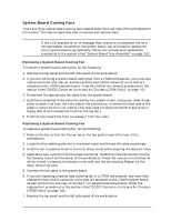 109
109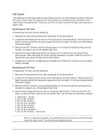 110
110 111
111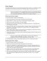 112
112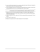 113
113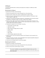 114
114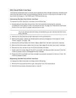 115
115 116
116 117
117 118
118 119
119