HP Visualize J7000 Overview of the Visualize fx graphics - Page 3
Occlusion Culling - prices
 |
View all HP Visualize J7000 manuals
Add to My Manuals
Save this manual to your list of manuals |
Page 3 highlights
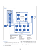
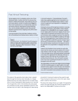
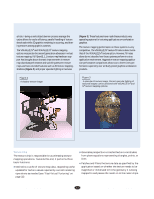
Occlusion Culling The HP fast-break program (page 8) enabled us to understand customer requirements by analyzing what is important in OpenGL graphics today. As a result, we developed a technology called occlusion culling as an extension to OpenGL and implemented it in the VISUALIZE fx graphics hardware. We found that the data sets many graphics workstation customers are trying to visualize are very complex. These data sets have large numbers of small, complex components that are not always visible in the final images. For instance, when rendering an airplane, all of the MCAD parts are present in the data set represented by potentially millions of polygons that must be processed. However, when this airplane is viewed from the outside only the outer surfaces are visible, not the fan blades of the engine or the seats or bulkheads in the interior. In a traditional 3D z-buffered graphics system, all polygons in a scene must be processed by the graphics pipeline because it is not known a priori which polygons will be visible and which ones will be occluded (not visible). The notion of occlusion culling, or removal of occluded objects, has been talked about in the research community for several years. However, implementations tend to be in software where the performance is not at a satisfactory level. In the VISUALIZE fx series of graphics devices, HP developed a very efficient algorithm that tests objects for visibility. An application program can very quickly use the occlusion culling visibility test to determine if a simple bounding box representation of a more complex part is visible. Since a bounding box, or more generally a bounding volume, completely encloses the more complex part, it is possible to know a priori that if the bounding volume is not visible then the complex part it encloses is not visible. Thus, the part that is not visible does not need to be processed through the graphics pipeline. The real benefit of occlusion culling comes when a very complex part consisting of many vertices can be rejected, avoiding the expenditure of valuable time to process it. For very complex data sets, such as the airplane mentioned above or an automobile, a tremendous performance increase can be realized by using the HP occlusion culling technology. To date, several ISVs have begun using occlusion culling in their applications and are seeing a 25 to 100 percent increase in graphics performance. This magnitude of performance benefit typically costs a customer several thousand dollars for the extra computational horsepower. HP includes this technology as standard in all VISUALIZE fx series graphics accelerators, giving even better price and performance results to our customers. The future of 3D graphics will continue toward visualizing ever more complex objects and environments. Occlusion culling together with HP's DirectModel technology (page 19) are well positioned to be industry leaders in providing the technology for 3D modeling applications. The primary responsibility of the interface chip is to separate the streams of data that arrive from the host SPU into three paths and arbitrate access among those paths. 3D Path. Typically data from the host CPU looks very much like the OpenGL API functions themselves. Data following this first path is routed to the geometry chips. The geometry chips process the data and return the results to the interface chip. These results are then sent on to the texture chips or directly to the raster chips if the texture mapping subsystem is not installed. In either case the data is transmitted to and through all the texture and raster chips in the system. Unbuffered Path. This path passes data directly through the interface chip to the texture and raster chips. This provides a bypass method that allows traffic to get around other pending operations. An example would be a texture cache download that is required to complete a primitive that is currently being rasterized, a situation that would lead to deadlock without the unbuffered path. 2D Path. This path runs directly through the interface chip to the texture and raster chips. The 2D path differs from the unbuffered path in the way its priority is handled. The interface chip manages priority among the three paths as they all converge on the same set of wires between the interface chip and the first texture chip. The unbuffered path goes directly through the interface chip to those wires and has priority over the other two paths. Data targeting the 2D path is held off until all preceding 3D work in the geometry chip has been flushed through to the first texture chip. Article 4 • © 1998 Hewlett Packard Company 30 May 1998 • The Hewlett-Packard Journal
-
 1
1 -
 2
2 -
 3
3 -
 4
4 -
 5
5 -
 6
6 -
 7
7
 |
 |
