HP Visualize J7000 Overview of the Visualize fx graphics - Page 4
X11 or other 2D APIs.
 |
View all HP Visualize J7000 manuals
Add to My Manuals
Save this manual to your list of manuals |
Page 4 highlights
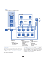
There is also special circuitry in the interface chip that is used to accelerate many operations commonly done by X11 or other 2D APIs. Buses The three primary buses in the system are each run at 200 MHz, allowing sustainable transfer rates of more than 800 Mbytes per second. To control the loading on the interconnections for these buses, they are built as point-to-point connections from one chip to the next. Each chip receives the signals and then retransmits them to the next chip in the sequence. This requires more pins on each part, but limits the number of loads on each wire to a single receiver as well as limiting the wiring length that signals must traverse. This allows for reliable communications despite the high frequency of the buses. The first of these three buses distributes work to the geometry chips. This bus starts at the interface chip and runs through all the geometry chips in the system. Each geometry chip monitors the data stream as it flows through the bus and picks off work to operate upon based on an algorithm that selects the least busy geometry chip. The second of these buses starts at the last geometry chip and passes through the others back to the interface chip. The results of the work done by the geometry chips is placed on this bus in the same sequence as it was moved along the first bus. This strict ordering control prevents certain artifacts from showing up in the final image. The third bus ties the interface chip to the texture and frame buffer subsystems. It is wired in a loop that goes back to the interface chip from the last chip in the chain. 3D operations typically flow from the interface chip to the chips along this bus, and when they eventually get back to the end of the loop, they are thrown away. For 2D operations, such as moving blocks of pixels around the frame buffer, the operation of the third bus is somewhat different. The movement of pixel data operates as a sequence of reads followed by a sequence of writes. The reads cause data to be dumped from the frame buffer locations onto the bus and the results travel back to the interface chip. This data is then associated with new addresses and sent as writes back down the bus, ending up back at the frame buffer but in different locations. Besides the three primary buses mentioned above, there are three secondary buses in the system. The first bus connects the interface chip to the video chip. This provides video control, download of color maps, and cursor control. The second bus is a connection from each raster chip to the video chip. This path is used to provide video refresh data to display frame buffer contents. The final secondary bus is a connection from each texture chip to two of the raster chips. This path allows the flow of filtered texture data into the raster chips for combination with nontexture fragment data. Geometry Chip The geometry and lighting chips are responsible for taking in geometric primitives (points, lines, triangles, and quadrilaterals) and executing all the operations associated with the transform stage of the graphics pipeline (see the article on page 9 for more about the graphics pipeline). These operations include: H Transformation of the coordinates from model space to eye space H Computing a vertex color based on the lighting state, which consists of up to eight directional or positional light sources H Texture map calculations that include: V Environment map calculations for texture mapping V Texture coordinate transformation V Linear texture coordinate generation V Texture projection H View volume clipping and clipping against six arbitrary application-specified planes to determine whether a primitive is completely visible, rejected because it is completely outside the view area, or needs to be reduced into its visible components H Perspective projection transformation to cause primitives to look smaller the further away from the eye they are H Setup calculations for rasterization in the raster chip. There were some interesting problems to solve in the design of the distribution and coalescing of work up and down the geometry chip daisy chain. For example, load balancing, maintaining strict order in the output stream, and ensuring that operations, such as binding of colors and normals to vertices, perform as required by OpenGL. Article 4 • © 1998 Hewlett Packard Company 31 May 1998 • The Hewlett-Packard Journal
-
 1
1 -
 2
2 -
 3
3 -
 4
4 -
 5
5 -
 6
6 -
 7
7
 |
 |