HP Xb3000 HP xb3000 Notebook Expansion Base - Maintenance and Service Guide - Page 13
Continued, Component, Function - hard drive carrier
 |
UPC - 882780374928
View all HP Xb3000 manuals
Add to My Manuals
Save this manual to your list of manuals |
Page 13 highlights
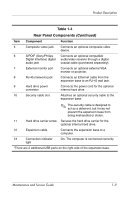
Product Description Table 1-4 Rear Panel Components (Continued) Item Component Function 5 Composite video jack Connects an optional composite video device. 6 S/PDIF (Sony/Philips Connects an optional compatible Digital Interface) digital audio/video receiver through a digital audio jack coaxial cable (purchased separately). 7 External monitor port Connects an optional external VGA monitor or projector. 8 RJ-45 (network) jack Connects an Ethernet cable from the expansion base to an RJ-45 wall jack. 9 Hard drive power connector Connects the power cord for the optional internal hard drive. 10 Security cable slot Attaches an optional security cable to the expansion base. ✎ The security cable is designed to act as a deterrent, but it may not prevent the expansion base from being mishandled or stolen. 11 Hard drive carrier screw Secures the hard drive carrier for the optional internal hard drive. 12 Expansion cable Connects the expansion base to a computer. 13 Connection indicator On: The computer is connected correctly. light *There are 2 additional USB ports on the right side of the expansion base. Maintenance and Service Guide 1-9
-
 1
1 -
2
-
3
-
4
-
5
-
6
-
7
-
 8
8 -
 9
9 -
 10
10 -
 11
11 -
 12
12 -
 13
13 -
 14
14 -
 15
15 -
 16
16 -
 17
17 -
 18
18 -
19
-
20
-
21
-
22
-
23
-
24
-
25
-
26
-
27
-
28
-
29
-
30
-
31
-
32
-
33
-
34
-
35
-
36
-
37
-
38
-
39
-
40
-
41
-
42
-
43
-
44
-
45
-
46
-
47
-
48
-
49
-
50
-
51
-
52
-
53
-
54
-
55
-
56
-
57
-
58
-
59
-
60
-
61
-
62
-
63
-
64
-
65
-
66
-
67
-
68
-
69
-
70
-
71
-
72
-
73
-
74
-
75
-
76
-
77
-
78
-
79
 |
 |
