HP Z200 Broadcom NetXtreme Gigabit Ethernet Plus Network Interface Card instal - Page 3
Step 1—Preparing for component installation, Download and install updates - manual
 |
View all HP Z200 manuals
Add to My Manuals
Save this manual to your list of manuals |
Page 3 highlights
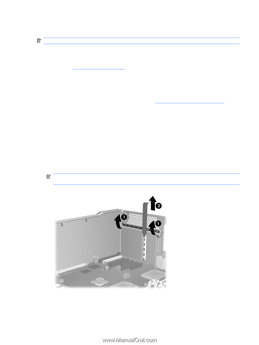
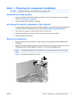
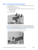
Step 1-Preparing for component installation NOTE: Computer models vary. All illustrations are examples only. Download and install updates 1. Check for available system BIOS updates specified for your HP computer model and operating system at http://www.hp.com/support. 2. Install the system BIOS updates, if available. Accessing the internal components of the computer 1. If you need help preparing the computer for this installation, consult the removal and replacement procedures in the service guide for your computer at http://www.hp.com/support/manuals. 2. Power down the computer, and then disconnect the power cord. 3. Power down all external devices, and then disconnect them from the computer. 4. Remove the side access panel. Removing components 1. If present, remove the card support to enable access to the expansion slots and system board connectors. 2. Select the smallest available expansion slot for a PCIe expansion card and remove the slot cover. The Broadcom NIC can be installed in a PCIe x1, x4, x8, or a x16 expansion slot. NOTE: To identify an available PCIe expansion slot, see the service label on the side access panel. Figure 1 Removing the expansion slot cover ENWW Step 1-Preparing for component installation 3
-
 1
1 -
 2
2 -
 3
3 -
 4
4 -
 5
5 -
 6
6
 |
 |