HP Z600 HP xw and Z Series Workstations - Internal USB port kit installation - Page 3
Step 1—Preparing for component installation, Accessing the internal components of the computer - manual
 |
UPC - 884962074053
View all HP Z600 manuals
Add to My Manuals
Save this manual to your list of manuals |
Page 3 highlights
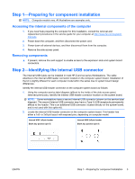
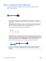
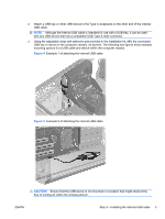
Step 1-Preparing for component installation NOTE: Computer models vary. All illustrations are examples only. Accessing the internal components of the computer 1. If you need help preparing the computer for this installation, consult the removal and replacement procedures in the service guide for your computer at http://www.hp.com/support/ manuals. 2. Power down the computer, and then disconnect the power cord. 3. Power down all external devices, and then disconnect them from the computer. 4. Remove the side access panel. Removing components ▲ If present, remove the card support to enable access to the expansion slots and system board connectors. Step 2-Identifying the internal USB connector The Internal USB Cable can be installed in most HP Z and xw series Workstations. The cable attaches to the internal USB header connector located on the computer system board. Installation of the kit is slightly different for each computer model within the series due to system board design differences. Identify the internal USB header connector on the computer system board as follows: 1. Using the computer service label diagram (affixed to the inside of the side access panel, removed previously), identify the internal USB header connector location on the system board. NOTE: Some workstations have a second Internal USB connector (shown on the service label diagram). The second Internal USB connector may have a Type A USB receptacle permanently affixed to the header. This is an additional USB connector, located directly on the system board, and is not used with this option kit. 2. Locate the internal USB header connector on the computer system board. This header has either a 1x5- or 2x5-pin layout with exposed pins, depending on computer model. Internal USB 1x5-pin header Blank key position (pin 5) Internal USB 2x5-pin header Blank key position (pin 9) ENWW Step 1-Preparing for component installation 3
-
 1
1 -
 2
2 -
 3
3 -
 4
4 -
 5
5 -
 6
6
 |
 |
