HP Z600 HP xw and Z Series Workstations - Internal USB port kit installation - Page 4
Step 3—Installing the internal USB cable, CAUTION
 |
UPC - 884962074053
View all HP Z600 manuals
Add to My Manuals
Save this manual to your list of manuals |
Page 4 highlights
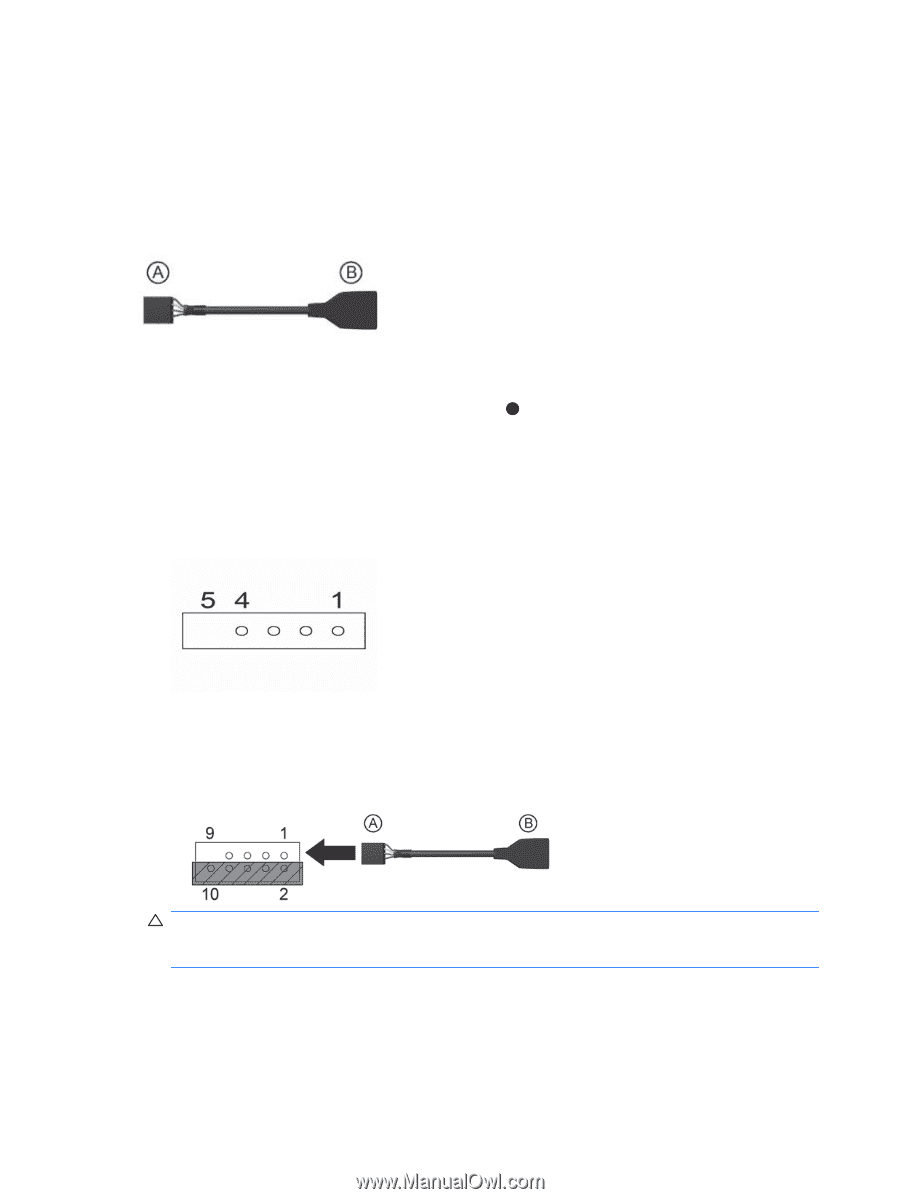
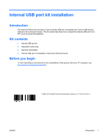
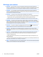
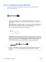
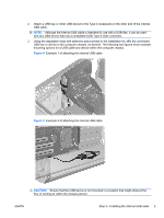
Step 3-Installing the internal USB cable Complete the following steps to install the internal USB cable, shown in the following figure. Figure 1 Internal USB cable 1. Attach the internal USB cable 1x5-pin receptacle ( A in the preceding figure) to the mating exposed pins of the available 1x5- or 2x5-pin header connector (which ever is available) on the system board: 1x5-pin header. When connecting the cable to a 1x5-pin header, carefully match the blank pin position on the header to the blank pin position on the cable receptacle. The following figure shows the pin blank pin position (pin 5) on the 1x5-pin header connector. Figure 2 1x5-pin header showing the blank pin 5 key position 2x5-pin header. When connecting the internal USB cable to a 2x5-pin header connector on the system board, carefully match the blank pin position on the header to the blank pin position on the cable receptacle, and connect the cable receptacle to the keyed side only of the header (containing pin positions 1, 3, 5, 7, and blank pin 9), as shown in the following figure. Figure 3 2x5-pin header showing the correct alignment and blank pin 9 key position CAUTION: Do not attempt to connect the internal USB cable receptacle to system board header pins 2, 4, 6, 8, and 10. Damage might result to the header connector and cable receptacle. 4 Internal USB port kit installation ENWW
-
 1
1 -
 2
2 -
 3
3 -
 4
4 -
 5
5 -
 6
6
 |
 |