HP dx2100 HP Compaq dx2100 MT Series PC Service Reference Card, 1st Edition - Page 2
Failsafe Boot Block ROM, Security Functions, Security Features, Diagnostic Functions - ram upgrade
 |
View all HP dx2100 manuals
Add to My Manuals
Save this manual to your list of manuals |
Page 2 highlights
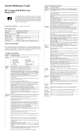
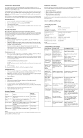
Failsafe Boot Block ROM The computer comes with a reprogrammable flash system ROM (read only memory). To upgrade the ROM, download the latest ROM BIOS image from the HP Web site (www.hp.com) and follow the online GUI/instructions. All ROM BIOS images from HP are digitally signed to ensure authenticity and minimize potential corruption. Your system ROM includes a Failsafe Boot Block that is protected during the flash process and allows the computer to be restarted in the unlikely event of an unsuccessful ROM flash. If the system detects an invalid system ROM during the boot sequence the system will search for a bootable device. To recover from the Boot Block recovery mode complete the following steps: Boot Block Recovery 1. Remove any bootable media from the computer and turn off power. 2. Insert a bootable diskette, or CD containing the ROM BIOS. 3. Turn on power to the system. 4. The system will automatically flash the ROM, load the BIOS default, and then boot to the operating system. Security Functions The system offers a single supervisor password for system and data protection. The password, if established, protects the computer from unauthorized access by prompting the user for a password during power up. The password, if established, protects the computer from unauthorized or inadvertent re-configuration by prompting the user for a password prior to entering the Setup Utility. Establishing a password: 1. Turn on or restart the computer. If you are in Windows, click Start > Shut Down > Restart the computer. 2. When the F10 Setup message appears in the lower-right corner of the screen, press the F10 key. Press Enter to bypass the title screen, if necessary. If you do not press F10 when prompted, a restart will be necessary. 3. Select Password Option, then select Change Supervisor Password and follow the instructions on the screen. You may also want to establish the Password check at this time. This will allow you to specify when the password will be required. 4. Before exiting, click File > Save Changes and Exit. Changing a password: 1. Turn on or restart the computer. If you are in Windows, click Start > Shut Down > Restart the Computer. To change the setup password, run Computer Setup. 2. When the key icon appears, type your current password, a slash (/) or alternate de-limiter character, your new password, another slash (/) or alternate delimiter character, and your new password again as shown: current password/new password/new password. NOTE: Type the new password carefully since the actual characters do not appear on the screen. 3. Press the enter key. The new password will take effect the next time the computer is restarted. Deleting a password 1. Turn on or restart the computer. If you are in Windows, click Start > Shut Down > Restart the Computer. To delete the setup password, run Computer Setup (F10). 2. When the key icon appears, type your current password followed by a slash (/) or alternate delimiter character as shown. Example: currentpassword/ 3. Press the Enter key. Clearing CMOS 1. Shut down the system and disconnect the power cord from the power outlet. 2. Remove the chassis access panel. 3. On the system board, move the CMOS jumper from pins 2-3 to pins 1-2 4. Allow the jumper to remain in that position for at least 5 seconds then, return the jumper to pins 2-3. 5. Replace the chassis access panel and reconnect the power cord. 6. Turn on the computer and allow it to start. Security Features Feature Floppy drive controller Device Boot Disabling Security Option BIOS Write Protect USB Controller Purpose Prevents the transfer of data to or from the floppy drive. Prevents booting from and or all of these devices: Internal or external USB, Internal ODD, or Internal FDD Prevents use of computer until password is entered. Can apply to both initial startup and restart. Restricts ability to change ROM BIOS without approval. Allows you to disable or enable all USB devices. How It Is Established Setup Utilities Setup Utilities Setup Utilities Setup Utilities. Setup Utilities NOTE: For more information about Setup Utilities refer to the Computer Setup Menu on the previous page or in the Service Reference Guide. Diagnostic Functions Diagnostic functions are provided by the Setup Utility (in system ROM) and by Insight Diagnostics. Insight Diagnostics provides detailed system information including: • Processor type and speed • Memory amount, mapping, and integrity • Hardware peripheral availability/settings • Hard drive type, space used/available • System identification, asset tracking Insight Diagnostics may be pre installed on some models and can be downloaded free of charge from www.hp.com. Error Conditions and Messages Chassis Diagnostic LEDs Power LED Steady green Steady green for 3 seconds followed by a 1 second pause Blinks green @ 0.5 Hz Blinks green @ 0.5 Hz Off (clear) Blinks green 5 times @ 1 Hz * Blinks green 6 times @ 1 Hz * Blinks green 8 times @ 1 Hz* NOTE: * Repeated after 2 second pause Event System on (normal operation) System overheating. Suspend to RAM (some models) Normal Suspend Computer off Memory not seated / installed Graphics card error Invalid ROM Common POST Error Messages Screen Message Probable Cause Recommended Action Parity Error Fatal memory parity error. System halts after displaying this message. Reseat memory modules. Replace memory modules ... Master/... Slave Hard Disk Error (Primary/Secondary) Master/Slave hard drive could not be initialized by the BIOS. Reseat the device data and power cables. Replace the device data cable. Replace the device. Replace the system board. ...Master/Slave Drive - ATAPI Incompatible Device configured as a (Primary/Secondary) Master/Slave failed an ATAPI compatibility test. Replace the device. Replace the system board. SMART capable but Command Failed. SMART Command Failed BIOS unable to send a SMART message to the device. Backup the data on the hard drive. Replace the hard drive. SMART status Bad, Backup and replace. SMART Capable and Status Bad. SMART capable hard drive detects an imminent failure. Backup the data on the hard drive. Replace the hard drive. DMA-1 Error DMA-2 Error DMA Controller Error Error when initializing the DMA controller. Reconnect the cables on the peripheral device. Replace the data cable. Replace the device. Replace the system board. Checking BIOS could not write to the NVRAM...Update NVRAM block. Failed Change system board jumper JP2 to pins 2-3, then flash the system BIOS. Reset jumpers to 1-2. Replace the system board. NVRAM Ignored or NVRAM Bad NVRAM data used to store plug and play data was not used for system configuration in POST. Restart computer, access Computer Setup. Select Load Default Settings > Save and Exit. Change system board jumper JP2 to pins 2-3, then flash the BIOS. Reset jumpers to 1-2. NVRAM Error detected while Checksum Bad, validating NVRAM data. NVRAM Cleared Restart the computer, use the F10 Key to access Computer Setup, Select Load Default Settings > Save and Exit. Microcode Error BIOS could not find or load CPU microcode to update the CPU. Ensure the system board BIOS supports the processor. Change system board jumper JP2 to pins 2-3, then flash the BIOS. Reset jumpers to 1-2.
-
 1
1 -
 2
2
 |
 |