HP dx7300 HP Compaq dx7300 and dc7700 Business PC Technical Reference Guide, 1 - Page 66
Non-Maskable Interrupts, Table 4-8., Maskable Interrupt Control Registers
 |
View all HP dx7300 manuals
Add to My Manuals
Save this manual to your list of manuals |
Page 66 highlights
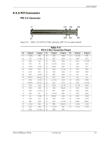
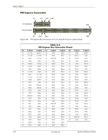
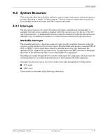
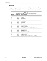
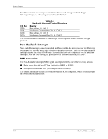
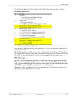
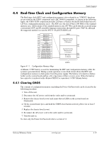
System Support Maskable Interrupt processing is controlled and monitored through standard AT-type I/O-mapped registers. These registers are listed in Table 4-8. I/O Port 020h 021h 0A0h 0A1h Table 4-8. Maskable Interrupt Control Registers Register Base Address, Int. Cntlr. 1 Initialization Command Word 2-4, Int. Cntlr. 1 Base Address, Int. Cntlr. 2 Initialization Command Word 2-4, Int. Cntlr. 2 The initialization and operation of the interrupt control registers follows standard AT-type protocol. Non-Maskable Interrupts Non-maskable interrupts cannot be masked (inhibited) within the microprocessor itself but may be maskable by software using logic external to the microprocessor. There are two non-maskable interrupt signals: the NMI- and the SMI-. These signals have service priority over all maskable interrupts, with the SMI- having top priority over all interrupts including the NMI-. NMI- Generation The Non-Maskable Interrupt (NMI-) signal can be generated by one of the following actions: ■ Parity errors detected on a PCI bus (activating SERR- or PERR-). ■ Microprocessor internal error (activating IERRA or IERRB) The SERR- and PERR- signals are routed through the ICH8 component, which in turn activates the NMI to the microprocessor. 4-14 www.hp.com Technical Reference Guide
-
 1
1 -
2
-
3
-
4
-
5
-
6
-
7
-
8
-
9
-
10
-
11
-
12
-
13
-
14
-
15
-
16
-
17
-
18
-
19
-
20
-
21
-
22
-
23
-
24
-
25
-
26
-
27
-
28
-
29
-
30
-
31
-
32
-
33
-
34
-
35
-
36
-
37
-
38
-
39
-
40
-
41
-
42
-
43
-
44
-
45
-
46
-
47
-
48
-
49
-
50
-
51
-
52
-
53
-
54
-
55
-
56
-
57
-
58
-
59
-
60
-
 61
61 -
 62
62 -
 63
63 -
 64
64 -
 65
65 -
 66
66 -
 67
67 -
 68
68 -
 69
69 -
 70
70 -
 71
71 -
72
-
73
-
74
-
75
-
76
-
77
-
78
-
79
-
80
-
81
-
82
-
83
-
84
-
85
-
86
-
87
-
88
-
89
-
90
-
91
-
92
-
93
-
94
-
95
-
96
-
97
-
98
-
99
-
100
-
101
-
102
-
103
-
104
-
105
-
106
-
107
-
108
-
109
-
110
-
111
-
112
-
113
-
114
-
115
-
116
-
117
-
118
-
119
-
120
-
121
-
122
-
123
-
124
-
125
-
126
-
127
-
128
-
129
-
130
-
131
-
132
-
133
-
134
-
135
-
136
-
137
-
138
-
139
-
140
-
141
-
142
-
143
-
144
-
145
-
146
-
147
-
148
-
149
-
150
-
151
-
152
-
153
-
154
-
155
-
156
-
157
-
158
-
159
-
160
-
161
-
162
-
163
-
164
-
165
-
166
-
167
-
168
-
169
-
170
-
171
-
172
-
173
-
174
-
175
-
176
-
177
-
178
-
179
-
180
-
181
-
182
-
183
-
184
-
185
-
186
-
187
-
188
-
189
-
190
-
191
-
192
-
193
-
194
-
195
-
196
 |
 |