HP mt40 HP mt40 Mobile Thin Client Maintenance and Service Guide IMPORTANT! Th - Page 67
straight up, and remove it., Lift the processor
 |
View all HP mt40 manuals
Add to My Manuals
Save this manual to your list of manuals |
Page 67 highlights
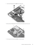
h. System board (see System board on page 53) i. Heat sink (see Heat sink on page 56) Remove the processor: 1. Use a flat-bladed screw driver (1) to turn the processor locking screw one-half turn counterclockwise, until you hear a click. 2. Lift the processor (2) straight up, and remove it. NOTE: The gold triangle (3) on the processor must be aligned with the triangle icon (4) embossed on the processor socket when you install the processor. Reverse this procedure to install the processor. Component replacement procedures 59
-
 1
1 -
2
-
3
-
4
-
5
-
6
-
7
-
8
-
9
-
10
-
11
-
12
-
13
-
14
-
15
-
16
-
17
-
18
-
19
-
20
-
21
-
22
-
23
-
24
-
25
-
26
-
27
-
28
-
29
-
30
-
31
-
32
-
33
-
34
-
35
-
36
-
37
-
38
-
39
-
40
-
41
-
42
-
43
-
44
-
45
-
46
-
47
-
48
-
49
-
50
-
51
-
52
-
53
-
54
-
55
-
56
-
57
-
58
-
59
-
60
-
61
-
 62
62 -
 63
63 -
 64
64 -
 65
65 -
 66
66 -
 67
67 -
 68
68 -
 69
69 -
 70
70 -
 71
71 -
 72
72 -
73
-
74
-
75
-
76
-
77
-
78
-
79
-
80
-
81
-
82
-
83
-
84
-
85
-
86
-
87
 |
 |

h.
System board (see
System board
on page
53
)
i.
Heat sink (see
Heat sink
on page
56
)
Remove the processor:
1.
Use a flat-bladed screw driver
(1)
to turn the processor locking screw one-half turn
counterclockwise, until you hear a click.
2.
Lift the processor
(2)
straight up, and remove it.
NOTE:
The gold triangle
(3)
on the processor must be aligned with the triangle icon
(4)
embossed on the processor socket when you install the processor.
Reverse this procedure to install the processor.
Component replacement procedures
59