HP rp4410 User Service Guide, Fifth Edition - HP 9000 rp4410/4440 - Page 122
Troubleshooting Using LED Indicators, Front Control Panel LEDs
 |
View all HP rp4410 manuals
Add to My Manuals
Save this manual to your list of manuals |
Page 122 highlights
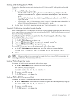
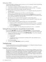
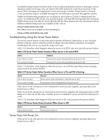
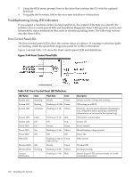
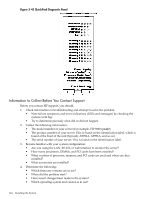
3. Using the BCH menu prompt, boot to the drive that contains the CD with the updated firmware. 4. To update the firmware, follow the on-screen installation instructions. Troubleshooting Using LED Indicators If you suspect a hardware failure during installation, the system LEDs help you identify the problem. Front control panel LEDs and QuickFind Diagnostic Panel LEDs provide system and subassembly status information that assist in identifying failing items. The following sections describe these LEDs. Front Control Panel LEDs The front control panel LEDs show the system status at a glance. If warning or attention lights are flashing, check the QuickFind diagnostic panel for further information. Figure 3-44 and Table 3-21 show the front control panel LED and definitions. Figure 3-44 Front Control Panel LEDs Table 3-21 Front Control Panel LED Definitions LED/Button System LED System LED System LED State Running Booting Attention Flash Rate Color Steady Green Flashing at 0.5 Hz Green Flashing at 1 Hz Yellow System LED System LED Power LED Power LED Power LED Disk LED Fault Off On On Off Thermal LED Thermal LED Locator LED/button OK Warning Flashing at 2 Hz Red Off N/A Steady Green Flashing at 1 Hz Yellow Off Off Flashing at rate of Green disk activity Steady Green Flashing at 1 Hz Yellow Flashing at 1 Hz Blue Description System normal-OS up and running. OS booting or at BCH. Warning-System needs attention. Redundancy lost, component failure pending. (Additional information can be found in the System Log). Hard fault, system halted. System off. Power normal. Housekeeping voltage present. Power off. Disk activity. Thermal OK. Thermal warning. System locator LED can be remotely or locally activated/deactivated. 122 Installing the System
-
 1
1 -
2
-
3
-
4
-
5
-
6
-
7
-
8
-
9
-
10
-
11
-
12
-
13
-
14
-
15
-
16
-
17
-
18
-
19
-
20
-
21
-
22
-
23
-
24
-
25
-
26
-
27
-
28
-
29
-
30
-
31
-
32
-
33
-
34
-
35
-
36
-
37
-
38
-
39
-
40
-
41
-
42
-
43
-
44
-
45
-
46
-
47
-
48
-
49
-
50
-
51
-
52
-
53
-
54
-
55
-
56
-
57
-
58
-
59
-
60
-
61
-
62
-
63
-
64
-
65
-
66
-
67
-
68
-
69
-
70
-
71
-
72
-
73
-
74
-
75
-
76
-
77
-
78
-
79
-
80
-
81
-
82
-
83
-
84
-
85
-
86
-
87
-
88
-
89
-
90
-
91
-
92
-
93
-
94
-
95
-
96
-
97
-
98
-
99
-
100
-
101
-
102
-
103
-
104
-
105
-
106
-
107
-
108
-
109
-
110
-
111
-
112
-
113
-
114
-
115
-
116
-
 117
117 -
 118
118 -
 119
119 -
 120
120 -
 121
121 -
 122
122 -
 123
123 -
 124
124 -
 125
125 -
 126
126 -
 127
127 -
128
-
129
-
130
-
131
-
132
-
133
-
134
-
135
-
136
-
137
-
138
-
139
-
140
-
141
-
142
-
143
-
144
-
145
-
146
-
147
-
148
-
149
-
150
-
151
-
152
-
153
-
154
-
155
-
156
-
157
-
158
-
159
-
160
-
161
-
162
-
163
-
164
-
165
-
166
-
167
-
168
-
169
-
170
-
171
-
172
-
173
-
174
-
175
-
176
-
177
-
178
-
179
-
180
-
181
-
182
-
183
-
184
-
185
-
186
-
187
-
188
-
189
-
190
-
191
-
192
-
193
-
194
-
195
-
196
-
197
-
198
-
199
-
200
-
201
-
202
-
203
-
204
-
205
-
206
-
207
-
208
-
209
-
210
-
211
-
212
-
213
-
214
-
215
-
216
-
217
-
218
-
219
-
220
-
221
-
222
-
223
-
224
-
225
-
226
-
227
-
228
-
229
-
230
-
231
-
232
-
233
-
234
-
235
-
236
-
237
-
238
-
239
-
240
-
241
-
242
-
243
-
244
-
245
-
246
 |
 |
