HP rp4410 User Service Guide, Fifth Edition - HP 9000 rp4410/4440 - Page 199
Replacing the SCSI Backplane, Installing the SCSI Duplex Board
 |
View all HP rp4410 manuals
Add to My Manuals
Save this manual to your list of manuals |
Page 199 highlights
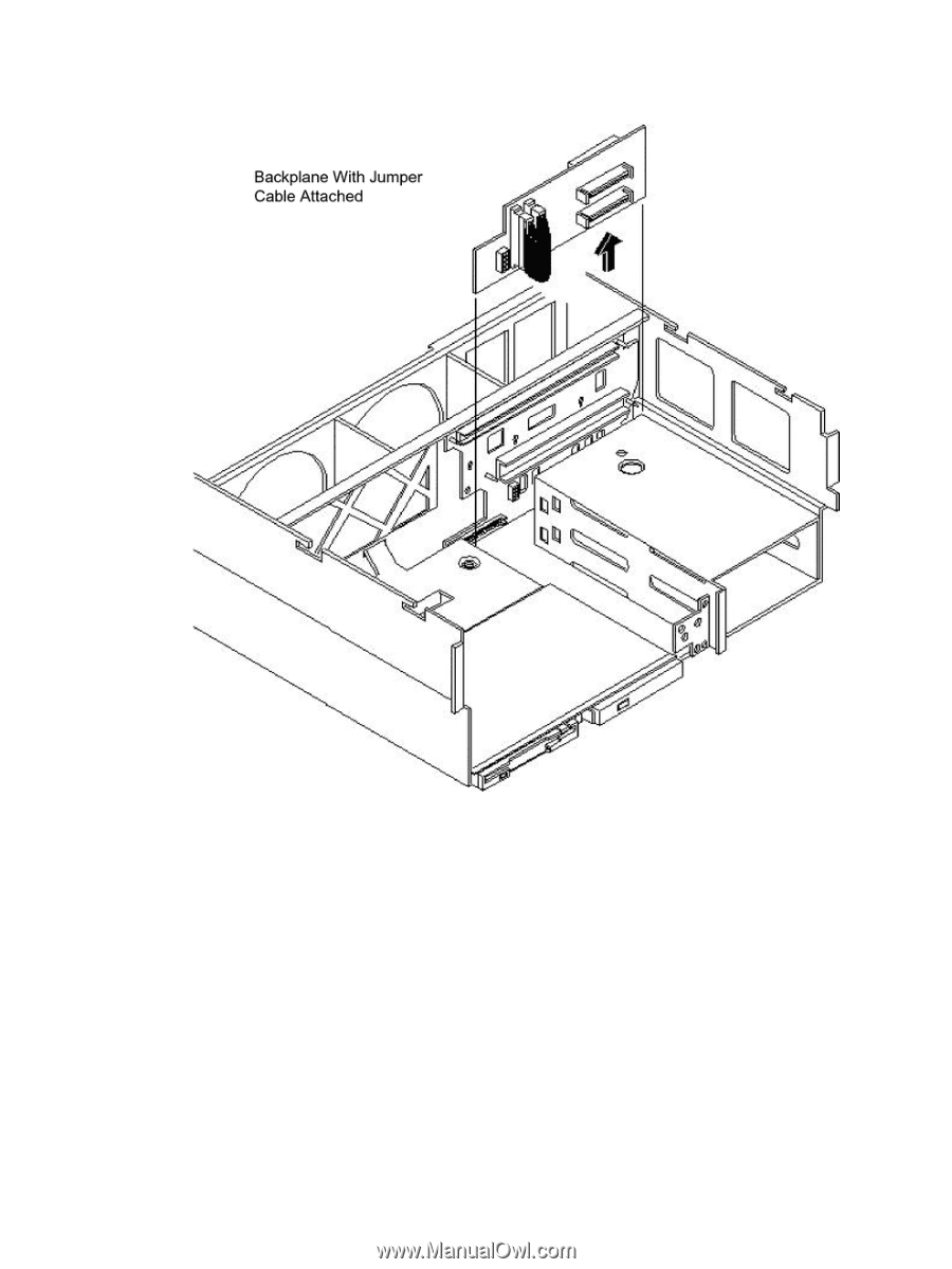
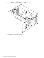
7. Push the SCSI backplane away from the disk drive cage and lift it up and out of the chassis. Figure 6-36 Lifting the SCSI Backplane Out of the Chassis Replacing the SCSI Backplane To replace the SCSI backplane, follow these steps: 1. Replace the SCSI backplane to the rear of the disk drive cage (HP part number A6961-04075). 2. If your system is configured for simplex operation, connect the SCSI jumper cable to the SCSI backplane connectors. 3. Plug the SCSI backplane-to-midplane cable back into the SCSI backplane. 4. Plug the internal SCSI cable into the SCSI back plane. If the server is configured for simplex operation, continue the upgrade at "Installing the Server Components" (page 201) Installing the SCSI Duplex Board Install the SCSI duplex board only if your system is configured for duplex operation. To install the duplex board, follow these steps: U320 SCSI Enablement and Conversion Procedures 199
-
 1
1 -
2
-
3
-
4
-
5
-
6
-
7
-
8
-
9
-
10
-
11
-
12
-
13
-
14
-
15
-
16
-
17
-
18
-
19
-
20
-
21
-
22
-
23
-
24
-
25
-
26
-
27
-
28
-
29
-
30
-
31
-
32
-
33
-
34
-
35
-
36
-
37
-
38
-
39
-
40
-
41
-
42
-
43
-
44
-
45
-
46
-
47
-
48
-
49
-
50
-
51
-
52
-
53
-
54
-
55
-
56
-
57
-
58
-
59
-
60
-
61
-
62
-
63
-
64
-
65
-
66
-
67
-
68
-
69
-
70
-
71
-
72
-
73
-
74
-
75
-
76
-
77
-
78
-
79
-
80
-
81
-
82
-
83
-
84
-
85
-
86
-
87
-
88
-
89
-
90
-
91
-
92
-
93
-
94
-
95
-
96
-
97
-
98
-
99
-
100
-
101
-
102
-
103
-
104
-
105
-
106
-
107
-
108
-
109
-
110
-
111
-
112
-
113
-
114
-
115
-
116
-
117
-
118
-
119
-
120
-
121
-
122
-
123
-
124
-
125
-
126
-
127
-
128
-
129
-
130
-
131
-
132
-
133
-
134
-
135
-
136
-
137
-
138
-
139
-
140
-
141
-
142
-
143
-
144
-
145
-
146
-
147
-
148
-
149
-
150
-
151
-
152
-
153
-
154
-
155
-
156
-
157
-
158
-
159
-
160
-
161
-
162
-
163
-
164
-
165
-
166
-
167
-
168
-
169
-
170
-
171
-
172
-
173
-
174
-
175
-
176
-
177
-
178
-
179
-
180
-
181
-
182
-
183
-
184
-
185
-
186
-
187
-
188
-
189
-
190
-
191
-
192
-
193
-
 194
194 -
 195
195 -
 196
196 -
 197
197 -
 198
198 -
 199
199 -
 200
200 -
 201
201 -
 202
202 -
 203
203 -
 204
204 -
205
-
206
-
207
-
208
-
209
-
210
-
211
-
212
-
213
-
214
-
215
-
216
-
217
-
218
-
219
-
220
-
221
-
222
-
223
-
224
-
225
-
226
-
227
-
228
-
229
-
230
-
231
-
232
-
233
-
234
-
235
-
236
-
237
-
238
-
239
-
240
-
241
-
242
-
243
-
244
-
245
-
246
 |
 |