HP t200 HP MultiSeat ms6200 Desktop and HP t200 Zero Client for MultiSeat Main - Page 79
System Board
 |
View all HP t200 manuals
Add to My Manuals
Save this manual to your list of manuals |
Page 79 highlights
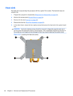
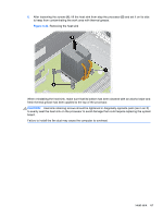
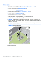
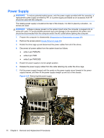
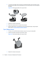
To install the power supply, reverse the removal procedure. CAUTION: When installing the power supply cables, make sure they are properly positioned so they are not cut by the drive cage and are not pinched by the rotating power supply. System Board 1. Prepare the computer for disassembly (Preparation for Disassembly on page 38). 2. Remove the access panel (Access Panel on page 39). 3. When replacing the system board, make sure the following components are removed from the defective system board and installed on the replacement system board: ● Memory modules (seeMemory on page 41) ● Expansion cards (Expansion Card on page 44) ● Heat sink (Heat sink on page 66) ● Processor (Processor on page 68) 4. Remove the baffle from the chassis (Fan duct on page 59). 5. Remove the fan from the chassis (Front Fan Assembly on page 60). 6. Rotate the drive cage to its upright position. 7. Rotate the power supply to its full upright position. 8. Disconnect all data and power cables from the system board. 9. Disconnect the balance of the cables from the system board. 10. Remove the eight screws (1) that secure the system board to the chassis. System Board 71
-
 1
1 -
2
-
3
-
4
-
5
-
6
-
7
-
8
-
9
-
10
-
11
-
12
-
13
-
14
-
15
-
16
-
17
-
18
-
19
-
20
-
21
-
22
-
23
-
24
-
25
-
26
-
27
-
28
-
29
-
30
-
31
-
32
-
33
-
34
-
35
-
36
-
37
-
38
-
39
-
40
-
41
-
42
-
43
-
44
-
45
-
46
-
47
-
48
-
49
-
50
-
51
-
52
-
53
-
54
-
55
-
56
-
57
-
58
-
59
-
60
-
61
-
62
-
63
-
64
-
65
-
66
-
67
-
68
-
69
-
70
-
71
-
72
-
73
-
 74
74 -
 75
75 -
 76
76 -
 77
77 -
 78
78 -
 79
79 -
 80
80 -
 81
81 -
 82
82 -
 83
83 -
 84
84 -
85
-
86
-
87
-
88
-
89
-
90
-
91
-
92
-
93
-
94
-
95
-
96
-
97
-
98
-
99
-
100
-
101
-
102
-
103
-
104
-
105
-
106
-
107
-
108
-
109
-
110
-
111
-
112
-
113
-
114
-
115
-
116
-
117
-
118
 |
 |