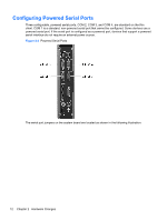
HP t505 Troubleshooting Guide t505 Flexible Thin Client - Page 19
WARNING, Serial Port Jumper Locations on the System Board
 |
View all HP t505 manuals
Add to My Manuals
Save this manual to your list of manuals |
Page 19 highlights
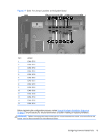
Figure 2-4 Serial Port Jumper Locations on the System Board Item 1 2 3 4 5 6 7 8 9 10 11 12 13 14 Jumper COM3 SP33 COM3 SP31 COM4 SP43 COM4 SP41 COM2 SP28 COM2 SP23 COM2 SP21 COM2 SP22 COM2 SP24 COM2 SP29 COM4 SP42 COM4 SP44 COM3 SP32 COM3 SP34 Before beginning the configuration process, review General Hardware Installation Sequence on page 7 for procedures you should follow before and after installing or replacing hardware. WARNING! Before removing the side access panel, ensure that the thin client is turned off and the power cord is disconnected from the electrical outlet. Configuring Powered Serial Ports 13
-
 1
1 -
2
-
3
-
4
-
5
-
6
-
7
-
8
-
9
-
10
-
11
-
12
-
13
-
 14
14 -
 15
15 -
 16
16 -
 17
17 -
 18
18 -
 19
19 -
 20
20 -
 21
21 -
 22
22 -
 23
23 -
 24
24 -
25
-
26
-
27
-
28
-
29
-
30
-
31
-
32
-
33
-
34
-
35
-
36
-
37
-
38
-
39
-
40
-
41
-
42
-
43
-
44
-
45
-
46
-
47
-
48
-
49
-
50
-
51
-
52
-
53
-
54
-
55
-
56
-
57
-
58
-
59
-
60
-
61
-
62
-
63
-
64
-
65
-
66
-
67
-
68
-
69
-
70
-
71
 |
 |
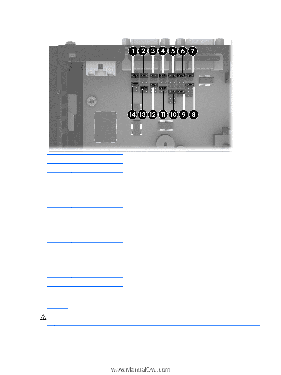
Figure 2-4
Serial Port Jumper Locations on the System Board
Item
Jumper
1
COM3 SP33
2
COM3 SP31
3
COM4 SP43
4
COM4 SP41
5
COM2 SP28
6
COM2 SP23
7
COM2 SP21
8
COM2 SP22
9
COM2 SP24
10
COM2 SP29
11
COM4 SP42
12
COM4 SP44
13
COM3 SP32
14
COM3 SP34
Before beginning the configuration process, review
General Hardware Installation Sequence
on page
7
for procedures you should follow before and after installing or replacing hardware.
WARNING!
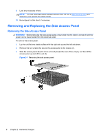
Before removing the side access panel, ensure that the thin client is turned off and the
power cord is disconnected from the electrical outlet.
Configuring Powered Serial Ports
13