HP t620 Hardware Reference Guide
HP t620 Manual
 |
View all HP t620 manuals
Add to My Manuals
Save this manual to your list of manuals |
HP t620 manual content summary:
- HP t620 | Hardware Reference Guide - Page 1
Hardware Reference Guide HP t620 Flexible Series Thin Client - HP t620 | Hardware Reference Guide - Page 2
notice. Microsoft and Windows are U.S. registered trademarks of Microsoft Corporation. The only warranties for HP products and services are set forth of Hewlett-Packard Company. Hardware Reference Guide HP t620 Flexible Series Thin Client Second Edition: November 2013 Document Part Number: 730525- - HP t620 | Hardware Reference Guide - Page 3
About This Book WARNING! Text set off in this manner indicates that failure to follow directions could result in bodily harm or loss of life. CAUTION: Text set off in this manner indicates that failure to follow directions could result in damage to equipment or loss of information. NOTE: Text set - HP t620 | Hardware Reference Guide - Page 4
iv About This Book - HP t620 | Hardware Reference Guide - Page 5
internal USB flash drives ...14 Installing additional memory ...16 SODIMMs ...16 DDR3L-SDRAM SODIMMs 16 Populating SODIMM sockets 17 Installing SODIMMs ...17 Installing a half-height PCI-Express 2.0 card 23 Security ...26 Hood sensor ...26 Cable lock ...27 Mounting the thin client ...28 Supported - HP t620 | Hardware Reference Guide - Page 6
38 Routine thin client care ...38 Supported orientations ...39 Non-supported orientation ...41 Appendix D Electrostatic discharge ...42 Preventing electrostatic damage ...42 Grounding methods ...42 Appendix E Shipping information ...43 Shipping preparation ...43 Important service repair information - HP t620 | Hardware Reference Guide - Page 7
list of the hardware and software installed on a specific model, visit http://www.hp.com and search for your specific thin client model. The following features are common to all HP thin clients: ● no hard drives or diskette drives ● 5 minutes or less hardware setup time ● central deployment and - HP t620 | Hardware Reference Guide - Page 8
to operation with a disabled write filter or enabled Page File, the damage will not be covered by HP warranty. For more information about write filter usage, see the operating system guide for your thin client available at http://www.hp.com/support/manuals/thinclients. NOTE: Your computer model may - HP t620 | Hardware Reference Guide - Page 9
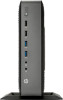
(6) USB 2.0 ports (2) (13) Power (7) Dual-mode DisplayPort 1.2 ports (2) (14) Cable lock slot *Available on some models. Refer to the model-specific QuickSpecs at www.hp.com for details. The devices connected at boot up or subsequently disconnected determine which video ports are enabled and - HP t620 | Hardware Reference Guide - Page 10
other software applications. (8) Editing keys Include the following: Insert, Home, Page Up, Delete, End, and Page Down. Hold Ctrl and Alt while pressing Delete to restart the thin client. 1Available in select geographic regions. 2For local sessions, applies only to thin clients running Windows - HP t620 | Hardware Reference Guide - Page 11
for a file or folder. Search for computers. Minimize all windows. Undo minimize all. Display the System Properties dialog box. Open the Run dialog box. Additional function keys The following key combinations also work on all thin clients regardless of operating system: Alt + Esc Alt + Tab Alt - HP t620 | Hardware Reference Guide - Page 12
Serial number location Every thin client includes a unique serial number located as shown in the following illustration. Have this number available when contacting HP customer service for assistance. 6 Chapter 1 Product features - HP t620 | Hardware Reference Guide - Page 13
workstation, setup, posture, and health and work habits for computer users, and provides important electrical and mechanical safety information. The Safety & Comfort Guide is located on the HP website at http://www.hp.com/ergo. WARNING! Energized and moving parts inside. Disconnect power to the - HP t620 | Hardware Reference Guide - Page 14
cord 1. Plug the female end of the power cord into the power supply brick (1). 2. Connect the other end of the power cord to an electrical outlet (2). 3. Connect the round end of the power supply cord to the power supply connector on the rear of the computer (3). 4. Use the slot (4) on the side - HP t620 | Hardware Reference Guide - Page 15
the computer. 2. Remove all removable media, such as USB flash drives, from the computer. 3. Turn off the computer properly through the operating system, and then turn off any external devices. 4. Disconnect the power cord from the power - HP t620 | Hardware Reference Guide - Page 16
important instructions and identification information, which may be lost if the access panel is not used. DO NOT use any access panel except the one that is provided by HP for use with this computer. Before removing the side access panel, be sure that the thin client is turned off and the power cord - HP t620 | Hardware Reference Guide - Page 17
state, voltage is always present on the system board as long as the system is plugged into an active AC outlet. You must disconnect the power cord to avoid damage to the internal components of the computer. 5. Remove the computer from the stand. 6. Lay the unit flat on a stable surface with - HP t620 | Hardware Reference Guide - Page 18
Replacing the access panel To replace the access panel: 1. Position the access panel (1) on the chassis, approximately 6 mm (.24 in) inside the edge of the chassis. Be sure that the access panel covers the hood sensor, and then slide the panel toward the front of the chassis (2) until it locks into - HP t620 | Hardware Reference Guide - Page 19
3. Insert the hooks on the right side of the I/O panel (1) into the right side of the back of the chassis, and then press the left side (2) to the chassis until it locks in place. Removing and replacing the access panel 13 - HP t620 | Hardware Reference Guide - Page 20
components to cool before you touch them. 7. If the computer is an HP t620 PLUS Thin Client, push the fan assembly latch (1) toward the front of the computer and rotate the assembly (2) up and out of the way. 8. Locate the USB flash drive ports on the system board. 14 Chapter 2 Hardware changes - HP t620 | Hardware Reference Guide - Page 21
installed does not exceed the maximum size for that USB port. 9. Align the USB flash drive with the USB port and press the drive firmly into the port until it is securely seated. 10. If the computer is an HP t620 PLUS Thin Client, rotate the fan assembly down, push the fan assembly latch (1) toward - HP t620 | Hardware Reference Guide - Page 22
13. Reconnect the power cord and turn on synchronous dynamic random access memory (DDR3LSDRAM) small outline dual inline memory modules (SODIMMs). SODIMMs The memory sockets at least one preinstalled SODIMM. To achieve the maximum memory support, you can populate the system board with up to 16 GB - HP t620 | Hardware Reference Guide - Page 23
with dual-sided SODIMMs, the system memory speed is reduced to 1333 MHz. Installing SODIMMs CAUTION: You must disconnect the power cord and wait approximately 30 seconds for the power to drain before adding or removing memory modules. Regardless of the power-on state, voltage is always supplied to - HP t620 | Hardware Reference Guide - Page 24
panel. See Removing and replacing the access panel on page 10. WARNING! To reduce risk of personal injury from hot surfaces, allow the internal system components to cool before you touch them. 7. If the computer is an HP t620 PLUS Thin Client, push the fan assembly latch (1) toward the front of the - HP t620 | Hardware Reference Guide - Page 25
memory compartment on the system board. 9. If a fiber NIC is installed, move the cable carefully out of the slot in the memory compartment cover. 10. Remove the two screws and springs (1) securing the memory compartment cover. NOTE: Be sure to retain the two screws and the springs beneath them. 11 - HP t620 | Hardware Reference Guide - Page 26
12. To remove a SODIMM, press outward on the two latches (1) on each side of the SODIMM, rotate the SODIMM up (2), and then pull the SODIMM out of the socket (3). 13. Slide the new SODIMM (1) into the socket at approximately a 30° angle, and then press the SODIMM into the socket (2) so that the - HP t620 | Hardware Reference Guide - Page 27
in the chassis, and then fasten the two screws (2) with the springs to secure the memory compartment cover. 17. If the computer is an HP t620 PLUS Thin Client, rotate the fan assembly down, push the fan assembly latch (1) toward the front of the computer, lower the assembly (2) until it stops, and - HP t620 | Hardware Reference Guide - Page 28
20. Reconnect the power cord and turn on the computer. 21. Lock any security devices that were disengaged when the computer cover or access panel was removed. The computer automatically recognizes the additional memory when you turn on the computer. 22 Chapter 2 Hardware changes - HP t620 | Hardware Reference Guide - Page 29
HP t620 PLUS Thin Client. A riser card is installed in this computer by default USB flash drives, from the computer. 3. Turn off the computer properly through the operating system, and then turn off any external devices. 4. Disconnect the power cord from the power access panel on page 10. 7. Push the - HP t620 | Hardware Reference Guide - Page 30
8. Locate the slot in the riser card. 9. Slide the expansion slot cover left and remove it. 24 Chapter 2 Hardware changes - HP t620 | Hardware Reference Guide - Page 31
10. Align the PCIe card connectors with the slot in the riser card and latch the access panel, and then reinstall the I/O panel. 13. Replace the computer stand. 14. Reconnect the power cord and turn on the computer. 15. Lock any security devices that were disengaged when the computer cover or access - HP t620 | Hardware Reference Guide - Page 32
The thin client is equipped with a hood sensor. You may also use a cable lock to secure the computer. For an additional layer of security, you may purchase a port cover to prevent unauthorized access to the rear ports. Hood sensor The hood sensor is a combination of hardware and software technology - HP t620 | Hardware Reference Guide - Page 33
security cable lock. This cable lock prevents unauthorized removal of the thin client, as well as locking devices installed inside the case. To order this option, visit the HP website at http://www.hp.com and search for your specific thin client model. 1. Locate the cable lock slot on the back panel - HP t620 | Hardware Reference Guide - Page 34
), such as flat-panel monitors, flat displays, and flat TVs. The HP Quick Release connects to the VESA-standard mounting points, allowing you to mount the thin client in a variety of orientations. NOTE: When mounting to a thin client, use the 15 mm screws supplied with the HP Quick Release. To use - HP t620 | Hardware Reference Guide - Page 35
15 mm screws included in the mounting device kit, attach one side of the HP Quick Release to the thin client as shown in the following illustration. 3. Using four screws included in the mounting device kit, attach the other side of the HP Quick Release to the device to which you will mount the - HP t620 | Hardware Reference Guide - Page 36
Quick Release automatically locks in position. You only need to slide the lever to one side to remove the thin client. CAUTION: For proper function of the HP Quick Release and a secure connection of all components, both the release lever on one side of the mounting device and the rounded opening on - HP t620 | Hardware Reference Guide - Page 37
Supported mounting options The following illustrations demonstrate some of the supported mounting options for the mounting bracket. Mounting the thin client 31 - HP t620 | Hardware Reference Guide - Page 38
-specific QuickSpecs. Dimensions Width: HP t620 Thin Client Width: HP t620 PLUS Thin Client 40 mm 65 mm 1.57 in. 2.56 in. Depth 240 mm 9.45 in Height (without stand) 219.70 mm 8.65 In Height (with stand) 220 mm 8.66 in. Temperature Range (fanless design)* Operating** 10°C to 40°C 50 - HP t620 | Hardware Reference Guide - Page 39
ft per minute) 9144 m Power Supply HP t620 Thin Client Operating Voltage Range 100 VAC to 240 VAC Rated Line Frequency 50 Hz to 60 Hz Power Output (maximum) 65 W Rated Output Current (maximum) 3.33 A Output Voltage +19.5 V dc 10,000 ft 30,000 ft HP t620 PLUS Thin Client 100 VAC to 240 - HP t620 | Hardware Reference Guide - Page 40
panel, be sure that the thin client is turned off and the power cord is disconnected from the electrical outlet. To remove and replace the battery: 1. Remove/disengage any security devices that prohibit opening the computer. 2. Remove all removable media, such as USB flash drives, from the computer - HP t620 | Hardware Reference Guide - Page 41
7. If the computer is an HP t620 PLUS Thin Client, perform the following steps: a. Push the fan assembly latch (1) toward the front of the computer and rotate the assembly (2) up and out of the way. b. - HP t620 | Hardware Reference Guide - Page 42
board. 10. Unplug the battery cable connector from the system board. 11. Connect the cable connector from the new battery to the system board. 12. Carefully press the new battery down to adhere the battery securely to the system board. 13. If the computer is an HP t620 PLUS Thin Client, perform - HP t620 | Hardware Reference Guide - Page 43
installed, reinstall it. For instructions, see Installing a half-height panel. 15. Replace the computer stand. 16. Reconnect the power cord and turn on the computer. 17. Lock any security devices the public collection system or return them to HP, an authorized HP partner, or their agents. The Taiwan - HP t620 | Hardware Reference Guide - Page 44
with a disabled write filter or enabled Page File, the damage will not be covered by HP warranty. For more information about write filter usage, see the operating system guide for your thin client available at http://www.hp.com/support/manuals/thinclients. Routine thin client care Use the following - HP t620 | Hardware Reference Guide - Page 45
HP supports the following orientations for the thin client. CAUTION: You must adhere to HP-supported orientations to be sure that your thin client functions properly. NOTE: HP t620 standard (slim) chassis: HP recommends mounting the thin client in the vertical (tower) orientation, with the HP - HP t620 | Hardware Reference Guide - Page 46
40 Appendix C Thin client operation - HP t620 | Hardware Reference Guide - Page 47
to maintain operating temperature. Do not block the vents. Do not put thin clients in drawers or other sealed enclosures. Do not place a monitor or other object on top of the thin client. Thin clients require proper ventilation to maintain operating temperatures. Non-supported orientation 41 - HP t620 | Hardware Reference Guide - Page 48
a ground cord to a grounded Thin Client chassis. Wrist straps are flexible straps of 1 megohm +/- 10 percent resistance in the ground cords. HP authorized dealer, reseller, or service provider. NOTE: For more information about static electricity, contact an HP authorized dealer, reseller, or service - HP t620 | Hardware Reference Guide - Page 49
environmental nonoperating ranges, see Specifications on page 32 Important service repair information In all cases, remove and safeguard all external options before returning the thin client to HP for repair or exchange. In countries that support customer mail-in repair by returning the same unit - HP t620 | Hardware Reference Guide - Page 50
the right side up. 6. Remove the computer access panel and back I/O panel. See Removing and replacing the access panel on page 10. 7. If the computer is an HP t620 PLUS Thin Client, push the fan assembly latch (1) toward the front of the computer and rotate the assembly (2) up and out of the way - HP t620 | Hardware Reference Guide - Page 51
9. Carefully pull the SSD out of the socket. Store the SSD carefully until it can be installed in the returned computer. 10. Rotate the fan assembly down, push the fan assembly latch (1) toward the front of the computer, lower the assembly (2) until it stops, and then release - HP t620 | Hardware Reference Guide - Page 52
7, 10, 17, 23 HP Quick Release 30 installing SODIMMs 17 removing the battery 34 securing the power cable 8 static electricity 7 thin client orientation 39, 41 ventilation 41 write filter 2, 38 components front panel 2 keyboard 4 mouse 5 rear panel 3 D dimensions 32 dual-mode DisplayPort 1.2 ports - HP t620 | Hardware Reference Guide - Page 53
32 hardware 32 humidity 32 power output 33 power supply 33 rated output current 33 relative humidity 32 temperature 32 thin client 32 specifications, memory 16 SSD, removing 43 stand, attaching 9 supported mounting options 31 supported orientations 39 horizontal 39 under monitor stand 39 vertical 39
-
 1
1 -
 2
2 -
 3
3 -
 4
4 -
 5
5 -
 6
6 -
 7
7 -
8
-
9
-
10
-
11
-
12
-
13
-
14
-
15
-
16
-
17
-
18
-
19
-
20
-
21
-
22
-
23
-
24
-
25
-
26
-
27
-
28
-
29
-
30
-
31
-
32
-
33
-
34
-
35
-
36
-
37
-
38
-
39
-
40
-
41
-
42
-
43
-
44
-
45
-
46
-
47
-
48
-
49
-
50
-
51
-
52
-
53
 |
 |

Hardware Reference Guide
HP t620 Flexible Series Thin Client