Hitachi 50GX30B Owners Guide - Page 10
Rear Panel Jacks - how to connection
 |
View all Hitachi 50GX30B manuals
Add to My Manuals
Save this manual to your list of manuals |
Page 10 highlights
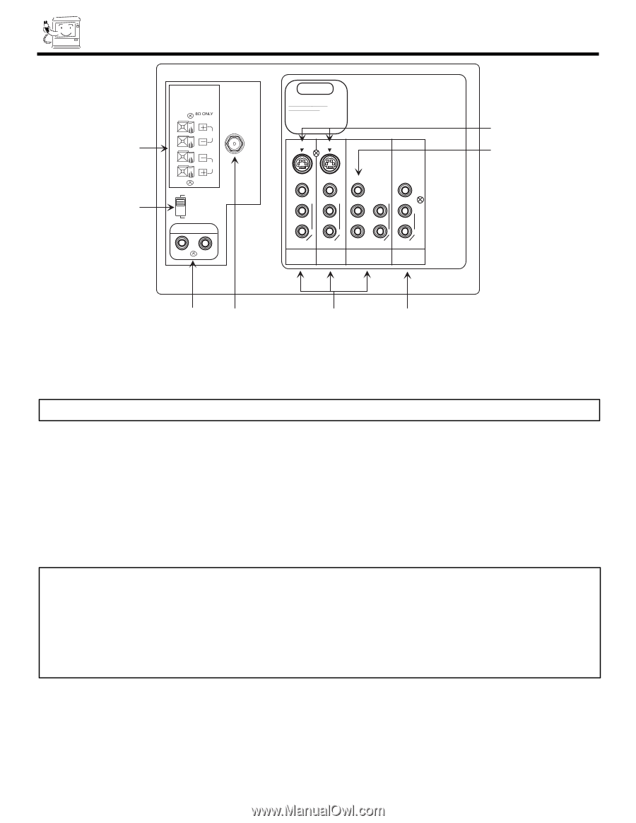
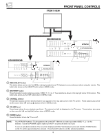
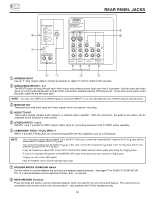
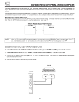
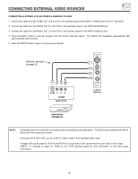
ᕊ ᕉ REAR SPEAKER VHF/UHF L R SP. MATRIX SURROUND EXT. AUDIO TO HI-FI REAR PANEL JACKS STOP CONNECT ONLY 8 OHM SPEAKERS DO NOT SHORT CIRCUIT THESE TERMINALS. (Such damage is NOT COVERED by your television warranty) S-VIDEO S-VIDEO VIDEO VIDEO Y/VIDEO VIDEO (MONO)/L (MONO)/L R R AUDIO AUDIO INPUT 1 INPUT 2 PB (MONO)/L L PR R R AUDIO AUDIO INPUT 4 MONITOR OUT ᕇ ቧ ᕆ ᕃ ᕄ ᕅ ቢ ANTENNA INPUT Use an F type coaxial cable to connect an antenna or cable TV (CATV) output to this rear jack. ባ AUDIO/VIDEO INPUTS 1, 2, 4 The INPUT button will step through each video source and antenna source input each time it is pressed. Use the audio and video inputs to connect external devices, such as VCRs, camcorders, laserdisc players, DVD players etc. (If you have mono sound, insert the audio cable into the left audio jack.) NOTE: You may use VIDEO or S-VIDEO inputs to connect to INPUT 1 or 2, but note that only one of these may be used at a time. ቤ MONITOR OUT These jacks provide fixed audio and video signals which are used for recording. ብ AUDIO TO HI-FI These jacks provide variable audio output to a separate stereo amplifier. With this connection, the audio to the stereo can be controlled by the television s main volume. ቦ S-VIDEO INPUTS 1 and 2 INPUTS 1 and 2 provides S-VIDEO (Super Video) jacks for connecting equipment with S-VIDEO output capability. ቧ COMPONENT VIDEO: Y-PBPR INPUT 4 INPUT 4 provides Y-PBPR jacks for connecting equipment with this capability, such as a DVD player. NOTE: Your component components R-Y outputs may be labeled Y, B-Y, output to the TV s PR input. and R-Y. In this case, connect the components B-Y output to the TV s PB input and the Your component outputs may be labeled ponents CR output to the TV s PR input. Y-CBCR. In this case, connect the components CB output to the TV s PB input and the com- It may be necessary to adjust TINT or turn AUTO COLOR-ON to obtain optimum picture quality when using the Y-PBPR inputs. To ensure no copyright infringement, the MONITOR OUT output will be abnormal, when using the Y-PBPR jacks. Y-PBPR can only receive 480i signals. Input 4 (Y/VIDEO) can be used for standard video input. ቨ SPEAKER MATRIX SURROUND Switch Use this switch to choose between the surround and external speaker features. See page 17 for AUDIO SYSTEM SETUP. The TV s Internal Speakers will be switched off when EXT. is selected. ቩ REAR SPEAKER Terminals These terminals are used to connect external speakers, which are used for the surround sound feature. The volume level is controlled by the remote control main volume buttons. Use speakers with 8 Ohm impedance only. 10
-
 1
1 -
2
-
3
-
4
-
 5
5 -
 6
6 -
 7
7 -
 8
8 -
 9
9 -
 10
10 -
 11
11 -
 12
12 -
 13
13 -
 14
14 -
 15
15 -
16
-
17
-
18
-
19
-
20
-
21
-
22
-
23
-
24
-
25
-
26
-
27
-
28
-
29
-
30
-
31
-
32
-
33
-
34
-
35
-
36
-
37
-
38
-
39
-
40
-
41
-
42
-
43
-
44
-
45
-
46
-
47
-
48
-
49
-
50
-
51
-
52
-
53
-
54
-
55
-
56
-
57
-
58
-
59
-
60
 |
 |