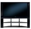
Hitachi 60VX915 Owners Guide - Page 23
Connecting Av Network - code
 |
View all Hitachi 60VX915 manuals
Add to My Manuals
Save this manual to your list of manuals |
Page 23 highlights
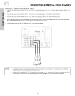
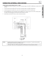
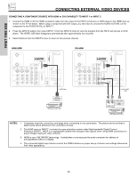
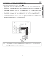
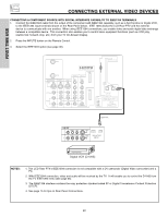
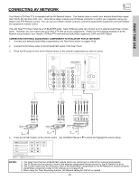
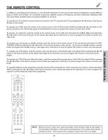
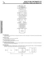
FIRST TIME USE CONNECTING AV NETWORK Your Hitachi LCD Rear PTV is equipped with an AV Network feature. This feature helps to control your external Audio/Video equipment (VCR, Set Top Box, DVD, etc.). Once this is setup, it allows your IR Mouse connector to control your equipment using your Hitachi LCD PTV Remote Control. You can use your Hitachi remote control to control the Audio/Video equipment command without the equipment's remote control. The LCD Rear PTV Rear Panel has 2 IR BLASTER jacks. Each IR Mouse cable can connect up to 2 external Audio/Video components. Therefore, you can connect the LCD Rear PTV with up to four components. Please see the following example of an AV Network setup between your Hitachi LCD Rear PTV and external Audio/Video equipment (VCR and DVD Player). CONNECTING EXTERNAL AUDIO/VIDEO COMPONENTS TO IR BLASTER FOR AV NETWORK 1. Connect your external Audio/Video components to the Rear Panel shown on pages 16-22. 2. Connect the IR Mouse cable to the IR BLASTER output of the Rear Panel. 3. Place the IR mouse in front of the infrared sensor of the external components you wish to control. ANT A CableCARD (Top of card faces right) ANT B MONITOR OUT S-VIDEO INPUT 4 INPUT 3 INPUT 2 Y/ VIDEO PB INPUT 1 Y/ VIDEO PB HDMI 1 VIDEO L AUDIO R AUDIO TO HI-FI PR PR (MONO) (MONO) (MONO) (MONO) TV AS CENTER HDMI 2 IEEE1394 IR BLASTER OPTICAL OUT Digital Audio Upgrade Card Apparatus Claims of U.S. Patent Nos. 4,631,603; 4,577,216; 4,819,098; 4,907,093; and 6,381,747 licensed for limited viewing uses only. RS232C 1 2 345 6 789 OUTPUT Y PB/CB PR/CR R L V L R OUTPUT V L R OUTPUT Infrared Sensor VCR #2 Infrared Sensor VCR Infrared Sensor DVD Player IR Mouse IR Mouse IR Mouse 4. Press the AV NET button on the remote control. Use CURSOR PAD ̆ or ̄ to select and highlight the Device Setup DVD POWER MENU DVD2 VCR VCR2 AV Receiver Move INFO Device Setting MORE NOTES: 1. The Rear Panel has two IR BLASTER outputs which can control up to a total of four external components. 2. The IR Mouse must be placed in front of the external components infrared sensor for the AV Network to work. 3. The correct codes must be entered for each of the Audio/Video components for the AV Network to function properly. 4. Audio/Video component codes for AV network are on page 25-26. 5. When using the Timer Recording function, AV Network setting for VCR #2 is needed. 23
-
 1
1 -
2
-
3
-
4
-
5
-
6
-
7
-
8
-
9
-
10
-
11
-
12
-
13
-
14
-
15
-
16
-
17
-
 18
18 -
 19
19 -
 20
20 -
 21
21 -
 22
22 -
 23
23 -
 24
24 -
 25
25 -
 26
26 -
 27
27 -
 28
28 -
29
-
30
-
31
-
32
-
33
-
34
-
35
-
36
-
37
-
38
-
39
-
40
-
41
-
42
-
43
-
44
-
45
-
46
-
47
-
48
-
49
-
50
-
51
-
52
-
53
-
54
-
55
-
56
-
57
-
58
-
59
-
60
-
61
-
62
-
63
-
64
-
65
-
66
-
67
-
68
-
69
-
70
-
71
-
72
-
73
-
74
-
75
-
76
-
77
-
78
-
79
-
80
-
81
-
82
-
83
-
84
-
85
-
86
-
87
-
88
-
89
-
90
-
91
-
92
-
93
-
94
-
95
-
96
 |
 |
