Hitachi DH18DLP4 Instruction Manual - Page 14
HOW TO USE
 |
UPC - 717709011649
View all Hitachi DH18DLP4 manuals
Add to My Manuals
Save this manual to your list of manuals |
Page 14 highlights
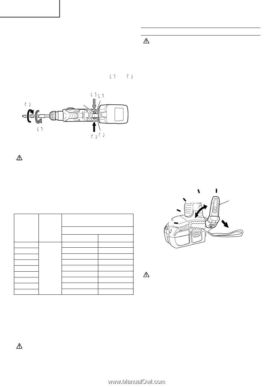
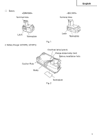
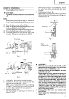
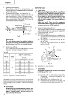
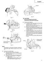
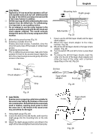
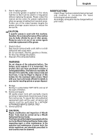
English 4. Selecting the driver bit Screw heads or bits will be damaged unless a bit appropriate for the screw diameter is employed to drive in the screws. 5. Confirm the direction of bit rotation (Fig. 9) The bit rotates clockwise (viewed from the rear side) by pushing the R-side of the push button. The L-side of the push button is pushed to turn the bit counterclockwise. (See Fig. 9) (The L and R marks are provided on the body.) L L marks R Push button L R R marks Fig. 9 CAUTION: The push button cannot be switched while the power tool is turning. To switch the push button, stop the power tool, then set the push button. 6. Continuous drilling The number of holes that can be drilled in concrete after one recharge is shown in Table 3. Table 3 Bit dia. (mm) *3.5 4 5 6 8 10 12 14 16 Depth (mm) 30 Possible continuous drilling number (holes) DH18DL Battery (EBM1830) Battery (BCL1815) 110 44 122 49 113 45 105 42 77 31 64 26 57 23 47 19 32 13 * Use an adapter for a small diameter bit. These data are for the referential values. The number of holes that can be drilled varies according to the sharpness of the used bit or the conditions of the concrete being drilled. HOW TO USE CAUTION: ⅜ When using the light equipped hook, pay sufficient attention so that the main equipment does not fall. If the tool falls, there is a risk of accident. ⅜ Do not attach the tip tool except phillips bit to the tool main unit when carrying the tool main unit with the light equipped hook suspended from a waist belt. Injury may result if you carry the equipment suspended from the waist belt with sharp tipped components such as drill bit attached. 1. Using the light equipped hook The light equipped hook can be installed on the right or left side and the angle can be adjusted in 5 steps between 0 and 80 . (1) Operating the hook (a) Pull out the hook toward you in the direction of arrow (A) and turn in the direction of arrow (B). (Fig.10) (b) The angle can be adjusted in 5 steps (0°, 20°, 40°, 60°, 80°). Adjust the angle of the hook to the desired position for use. 4 5 3 2 (B) Hook 1 (A) Fig. 10 (2) Switching the hook position CAUTION: Incomplete installation of the hook may result in bodily injury when used. (a) Securely hold the main unit and remove the screw using a slotted head screwdriver or a coin. (Fig. 11) (b) Remove the hook and spring. (Fig. 12) (c) Install the hook and spring on the other side and securely fasten with screw. (Fig. 13) CAUTION: When using this unit continuously, the unit may overheat, leading to damage in the motor and switch. Please leave it without using it for approximately 15 minutes. 14
-
 1
1 -
2
-
3
-
4
-
5
-
6
-
7
-
8
-
 9
9 -
 10
10 -
 11
11 -
 12
12 -
 13
13 -
 14
14 -
 15
15 -
 16
16 -
 17
17 -
 18
18 -
 19
19 -
20
-
21
-
22
-
23
-
24
-
25
-
26
-
27
-
28
-
29
-
30
-
31
-
32
-
33
-
34
-
35
-
36
-
37
-
38
-
39
-
40
-
41
-
42
-
43
-
44
-
45
-
46
-
47
-
48
-
49
-
50
-
51
-
52
-
53
-
54
-
55
-
56
-
57
-
58
-
59
-
60
-
61
-
62
-
63
-
64
-
65
-
66
-
67
-
68
-
69
-
70
-
71
-
72
 |
 |