Hitachi DV-PF33U Owners Guide - Page 13
Hookups
 |
View all Hitachi DV-PF33U manuals
Add to My Manuals
Save this manual to your list of manuals |
Page 13 highlights
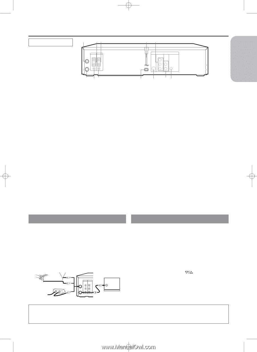
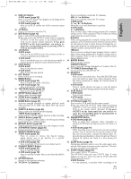
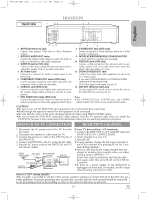
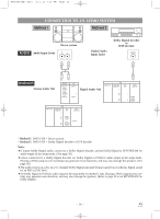
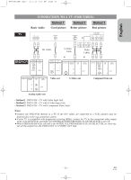
H9450UD(EN).qx33 03.1.22 7:19 PM Page 13 English REAR VIEW HOOKUPS 1 23 45 DVD/VCR VCR AUDIO OUT AUDIO IN ANT-IN L L R R ANT-OUT VIDEO OUT VIDEO IN DVD S-VIDEO COMPONENT AUDIO OUT VIDEO OUT OUT Y DIGITAL AUDIO OUT I P PROGRESSIVE CB PB L COAXIAL CR PR R 12 11 10 1. ANT-IN (Antenna In) Jack Connect your antenna, Cable Box, or Direct Broadcast System. 2. DVD/VCR AUDIO OUT Jacks Connect the supplied audio cables here and to the Audio In jacks of a television or other audio equipment. 3. AUDIO IN Jacks (VCR only) Connect audio cables coming from the audio out jacks of a camcorder, another VCR, or an audio source here. 4. AC Power Cord Connect to a standard AC outlet to supply power to the DVD/VCR. 5. COMPONENT VIDEO OUT Jacks (DVD only) Connect optional component video cables here and to the component Video In jacks of a television. 6. COAXIAL Jack (DVD only) Connect an optional coaxial digital audio cable here and to the Coaxial Digital Audio In jack of a decoder or audio receiver. 7. DVD AUDIO OUT Jacks (DVD only) Connect the supplied audio cables here and to the Audio In jacks of a television or other audio equipment (DVD only). 9 8 76 8. S-VIDEO OUT Jack (DVD only) Connect an optional S-Video cable here and to the S-Video In jack of a television. 9. INTERLACE/PROGRESSIVE SCAN SELECTOR to select interlace or progressive scanning. 10. VIDEO IN Jack (VCR only) Connect a cable coming from the video out jack of a camcorder, another VCR, or an audio-visual source (laser disc player, video disc player, etc.) here. 11. DVD/VCR VIDEO OUT Jack Connect the yellow video cable (supplied) here and to the TV's Video In jack. If you select P(PROGRESSIVE) in INTERLACE/PROGRESSIVE SCAN SELECTOR, DVD video signal is not output to your TV. 12. ANT-OUT (Antenna Out) Jack Use the supplied RF coaxial cable to connect this jack to the ANTENNA IN Jack on your TV. Notes ¡The S-VIDEO OUT jack, COAXIAL jack, amd COMPO- NENT VIDEO OUT jack are only useful in DVD mode. CAUTION: ¡Be sure to turn off the DVD/VCR and equipment to be connected before connecting. ¡Read through the operation manual for the equipment to be connected. ¡Be sure that the colors of the jacks and plugs match up when using VIDEO/AUDIO cables. ¡Be sure to keep the DVD/VCR connection cables separate from the TV antenna cable when you install the DVD/VCR, because it may cause electrical interference when you are watching television programs. DVD/VCR TO TV CONNECTION RF OUTPUT CHANNEL 1. Disconnect the AC power cord of the TV from the AC outlet. 2. Disconnect the antenna or cable from the TV. 3. Connect the antenna or cable to the ANT-IN jack of the DVD/VCR. 4. Connect the DVD/VCR to the TV using the RF cable. 5. Plug the AC power cords of the DVD/VCR and TV into the AC outlets. [VHF/UHF [Indoor antenna] combination antenna] OR [Cable box or satellite box] OR From Cable or Satellite Company IN OUT [Back of the DVD/VCR] [Back of the UHF/VHF combination TV] DVD/VCR VCR AUDIO OUT AUDIO IN ANT-IN L L RF cable (supplied) UHF/VHF R R ANT-OUT VIDEO OUT VIDEO IN If your TV does not have A/V terminals: 1. Connect the DVD/VCR to a TV using RF cable (see DVD/VCR TO TV CONNECTION). 2. Select channel 3 on your TV. 3. Press PLAY. ¡If noise appears, change the RF output channel of the VCR to channel 4 by pressing PLAY for 3 seconds during playback. ¡There is case that the RF output channel does not change by situation (For example, when you adjust tracking using CHANNEL ( ) . In this case, stop the playback, and start the playback again. After that, press PLAY on the VCR for 3 seconds. ¡If there is a power failure or the DVD/VCR is unplugged for more than 30 seconds, the RF output channel setting will return to CH3. Note to CATV system installer This reminder is provided to call the CATV system installer's attention to Article 820-40 of the NEC that provides guidelines for proper grounding and, in particular, specifies that the cable ground should be connected to the grounding system of the building, as close to the point of cable entry as practical. - 13 - EN 1L25
-
 1
1 -
2
-
3
-
4
-
5
-
6
-
7
-
 8
8 -
 9
9 -
 10
10 -
 11
11 -
 12
12 -
 13
13 -
 14
14 -
 15
15 -
 16
16 -
 17
17 -
 18
18 -
19
-
20
-
21
-
22
-
23
-
24
-
25
-
26
-
27
-
28
-
29
-
30
-
31
-
32
-
33
-
34
-
35
-
36
-
37
-
38
-
39
-
40
-
41
-
42
-
43
-
44
 |
 |