Hitachi M12SA2 Instruction Manual - Page 14
Adjusting the rotation speed Model, M12V2 only
 |
UPC - 717709010383
View all Hitachi M12SA2 manuals
Add to My Manuals
Save this manual to your list of manuals |
Page 14 highlights
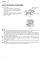
English When using the router along the interior plane of the template, the dimensions of the Template finished product will be less than the guide dimensions of the template by an amount equal to dimension "A", the difference Screw between the radius of the template guide and the radius of the bit. The reverse is true when using the router along the exterior of the template. (3) Straight guide (Fig.14) Fig. 12 Template guide adapter Use straight guide for chamfering and groove cutting along the materials side. 1 Insert the guide bar into the hole in the bar Template Bit Guide Template holder, then lightly tighten the 2 wing bolts (B) on top of the bar holder. 2 Insert the guide bar into the hole in the base, then firmly tighten the wing bolts (A) (standard accessories). 3 Make minute adjustments of the dimensions A between the bit and the guide surface with the feed screw, then firmly tighten the 2 Fig. 13 wing bolts (B) on top of the bar holder and the wing bolt (C) that secures the straight guide. Guide bar 4 As shown in Fig. 15, securely attach the bottom of the base to processed surface of the materials. Feed the router while keeping Wing the guide plane on the surface of the bolt (A) Wing bolt (B) materials. Straight (4) Dust guide and dust guide adapter (Fig. 16) guide Your router is equipped with a dust guide and a dust guide adapter. Feed screw Wing bolt (C) 1 Match the 2 grooves on the base and insert Guide plane Bar holder the 2 dust guide tabs in holes located in the base side from the top. Tighten the dust Fig. 14 guide with a screw. The dust guide diverts cutting debris away from the operator and directs the discharge in a consistent direction. 2 By fitting the dust guide adapter into the dust guide cutting debris discharge vent, the dust extractor can be attached. 4. Adjusting the rotation speed (Model M12V2 only) The M12V2 has an electronic control system that allows stepless rpm changes. As shown in Fig. 17, dial position "1" is for minimum speed, and position "6" for maximum Fig. 15 14 speed.
-
 1
1 -
2
-
3
-
4
-
5
-
6
-
7
-
8
-
 9
9 -
 10
10 -
 11
11 -
 12
12 -
 13
13 -
 14
14 -
 15
15 -
 16
16 -
 17
17 -
 18
18 -
 19
19 -
20
-
21
-
22
-
23
-
24
-
25
-
26
-
27
-
28
-
29
-
30
-
31
-
32
-
33
-
34
-
35
-
36
-
37
-
38
-
39
-
40
-
41
-
42
-
43
-
44
-
45
-
46
-
47
-
48
-
49
-
50
-
51
-
52
-
53
-
54
-
55
-
56
-
57
-
58
-
59
-
60
 |
 |
