Honeywell 5800RP Installation Guide - Page 2
Setting The Site Id, Led Functions, Programming And Operational Notes, Specifications - ademco
 |
UPC - 781410474901
View all Honeywell 5800RP manuals
Add to My Manuals
Save this manual to your list of manuals |
Page 2 highlights
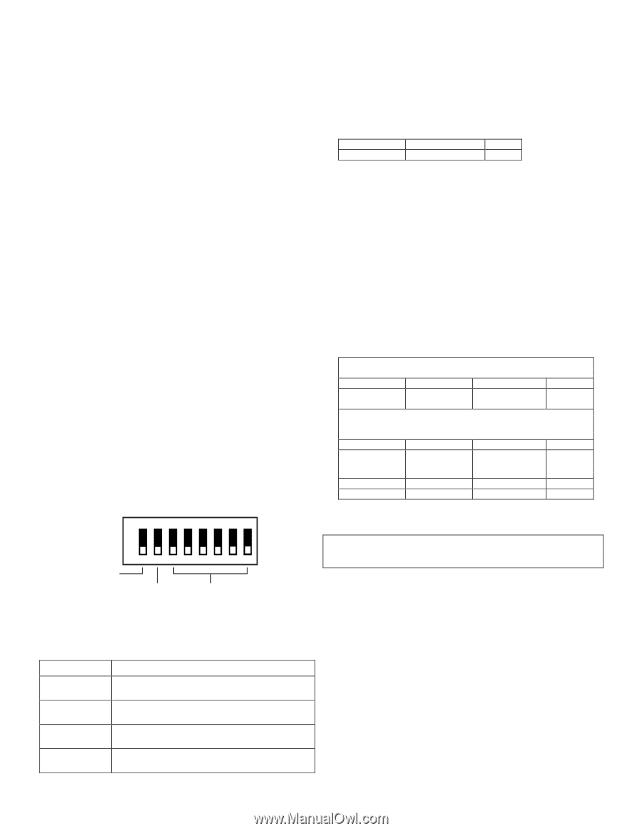
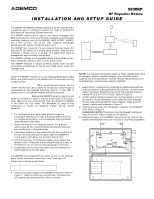
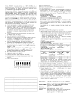
SETTING THE SITE ID Some ADEMCO wireless devices (e.g., 5827, 5804BD) use a programmed house ID to help avoid communication conflicts with nearby installations. The 5800RP automatically passes all house ID information to the appropriate receiver. Certain newer ADEMCO wireless devices, such as the 5883 and the 5839, use a "Site ID" instead of a House ID. The Site ID is a factory-assigned, unique serial number built into each 5883 transceiver and must be entered into each device that uses it. The Site ID provides many more combinations than a House ID, and therefore is less likely to have conflicts with nearby installations. When using the 5800RP with wireless devices that use a Site ID, follow the steps below to enter a permanent copy of the Site ID in the 5800RP. This procedure assumes that all such devices have been successfully set-up and tested with the 5883, although they may not yet be mounted in their final locations. 1. Put the control (and the 5883) in the Go/No Go Test mode. 2. Remove the 5800RP's cover by inserting and twisting a screwdriver blade in the slot at the center of the cover's lower edge. Note that removing the cover also places the 5800RP in the Go/No Go Test mode. This decreases its range during installation to insure an adequate margin during normal operation. 3. Temporarily disconnect the power supply and battery from the 5800RP. Refer to Figure 2. 4. Place DIP switch 1 in the ON position. 5. Reconnect the power supply to the 5800RP. Observe that the red LED on the 5800RP turns on and remains on. This indicates that the 5800RP is ready to set the Site ID. 6. Push and release the tamper switch on the 5800RP. This causes a set-up request message to be sent to the 5883. 7. Observe that the red LED turns off, indicating that the Site ID has been saved in the 5800RP. If not, repeat the previous step until it does. NOTE: If the tamper switch is not pushed for 1 minute or if DIP switch 1 is turned off, the red LED turns off. This indicates the 5800RP will no longer accept the Site ID. 8. Place DIP switch 1 in the OFF position. 9. Replace the cover on the 5800RP. 10. Take the control out of the Go/No Go Test mode. 11. If needed locate the other wireless devices in their final locations. 12. Test all wireless devices. ON PROGRAMMING AND OPERATIONAL NOTES Non-UL Installations (DIP switch 2 must be OFF during normal operation) 1. Set DIP switch 2 to OFF. 2. If module supervision is desired, assign the 5800RP to a zone for sending check-in, low battery†, AC loss, and RF jam messages, and enroll its serial number. When prompted, toggle the tamper switch to enroll the serial number. The yellow LED should blink on when messages are sent. Program the zone as follows: Zone Type Input Type Loop 8 (24-hour aux) 3 (supervised RF) 1 • The 5800RP reports AC loss and RF jam conditions as "low battery" status, which is also displayed on the control's keypads. This prevents either condition from causing an alarm when the control is armed. • The 5800RP will not repeat a message that has already been repeated. UL Installations (DIP switch 2 must be ON during normal operation) 1. Supervision: Module supervision is required using the module's built-in serial numbers, which are enrolled in 4 zones as follows: - Assign the first serial number to a zone for sending low battery† and supervision check-in messages. - Assign the second serial number to 3 zones for sending tamper, AC loss, and RF jam messages. When prompted, toggle the tamper switch to enroll the serial numbers. Program the zones as follows: First Serial Number Set DIP switch 2 to OFF, then enroll as follows: Zone Zone Type Input Type Loop Low Battery/ 8 3 - RF 1 Check-in Zone (24-hour aux) (supervised RF) Second Serial Number Set DIP switch 2 to ON, then enroll as follows: (keep switch 2 in the ON position when enrolling is complete) Zone Zone Type Input Type Loop Tamper Zone 5 4 - UR 1 (trouble by day / (unsupervised RF) alarm by night) AC Loss Zone 8 (24-hour aux) 4 - UR 2 RF Jam Zone 8 (24-hour aux) 4 - UR 3 For easy identification of these messages, program alpha descriptors at the control for each zone, using words such as "REPEATER LOW BATTERY, REPEATER AC LOSS, etc. 5800RP_dip-00-002-V0 1 2 34 56 7 8 SW-1 USED WHEN ENROLLING SITE ID; OTHERWISE MUST BE OFF MUST BE OFF FOR NON - UL; MUST BE ON FOR UL 3 - 8 NOT USED MUST BE OFF Figure 3 5800RP DIP Switch LED FUNCTIONS LED Activates Upon Green Normally on (lighted) when power (AC or battery) is present. Flickering indicates RF is being processed. Yellow Normally off. Blinks to indicate that an RF message is being sent by the 5800RP. Red Normally off. Turns on (lighted) when setting Site ID. See the Setting the Site ID section for details. Red Lights when RF activity is present. RF Interference † If an actual low battery condition is reported, it takes up to 12 hours after AC power is restored for the low battery restore message to be sent (requires 12 hours for fully recharged battery). 2. Power Supply: Use a class 2 Listed Burglar Alarm power supply for UL installations. 3. Control Panel's Current Drain Calculation: In order to properly choose the correct backup battery capacity for systems using a 5800RP in UL installations, use the connected keypad's maximum alarm (sounder on) current rating, not the keypad's standby current rating, when calculating the control panel's total current drain. This is necessary because AC loss at the 5800RP causes the keypad to beep. SPECIFICATIONS Dimensions: 7-3/8" W x 4-3/8" (10-7/8" w/antennas) H x 1-7/16" D. 188mm W x 112mm H (277mm w/antennas) x 37mm D. Input Voltage: 12VDC or 9VAC, 15VA (from separate power supply such as ADEMCO 1332). Current: 80mA Battery Pack: rechargeable, part number K0257 Range: 200ft (60m) nominal indoors from wireless devices (the actual range to be determined with the security system in the TEST mode). - 2 -
-
 1
1 -
 2
2 -
 3
3 -
 4
4
 |
 |