Honeywell 5819WHS Installation Instructions - Page 1
Honeywell 5819WHS - Ademco Wireless Shock Processor Manual
 |
UPC - 781410176225
View all Honeywell 5819WHS manuals
Add to My Manuals
Save this manual to your list of manuals |
Page 1 highlights
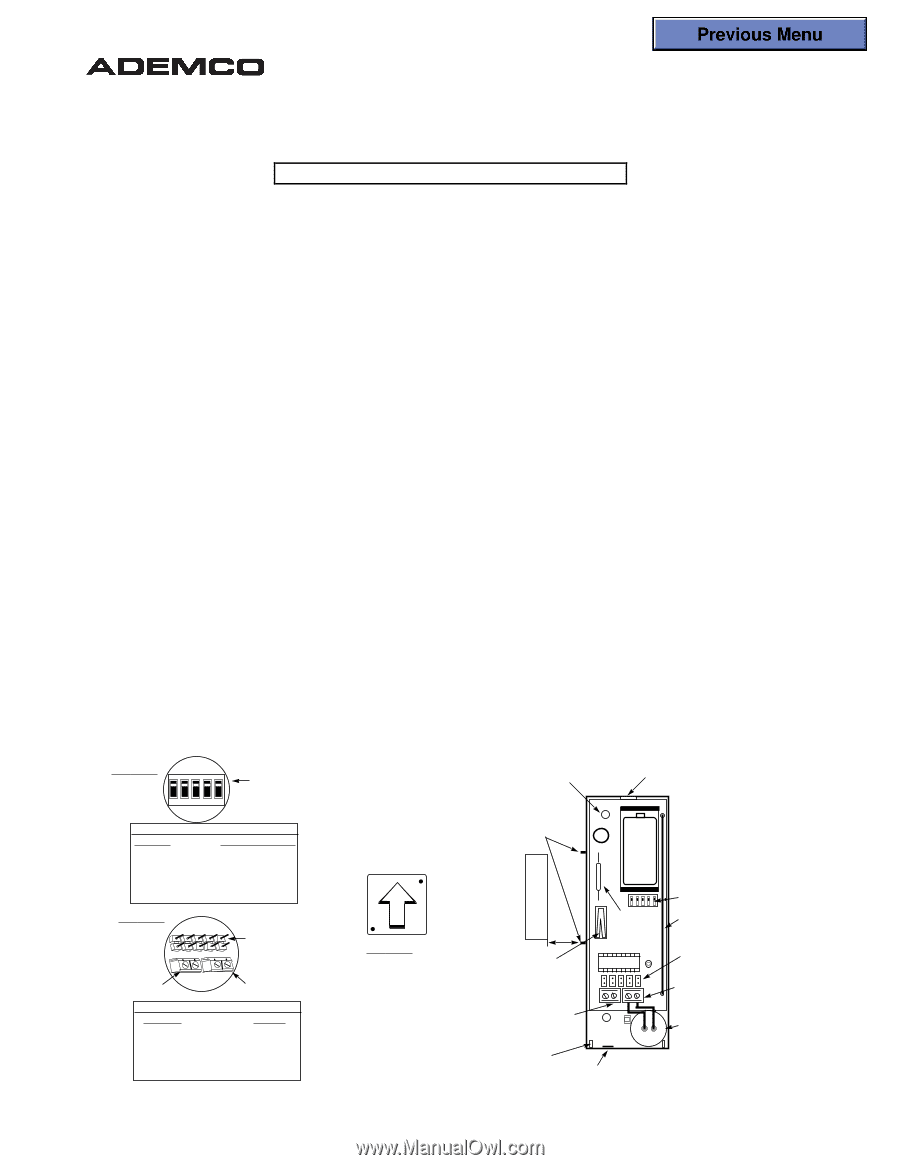
Previous Menu ® N7491-1V1 5/98 5819WHS/5819BRS SHOCK PROCESSOR TRANSMITTER INSTALLATION INSTRUCTIONS For use with QED control panels ONLY! GENERAL INFORMATION The 5819WHS/5819BRS Shock Processor Transmitters feature a built-in shock sensor and are intended for use only with a wireless alarm system that supports Ademco QED 5800 Series wireless receivers. The built-in shock sensor is used to detect forcible attack upon the surface to which it is mounted. It is designed to protect window and door surroundings. The sensor is electrically normally closed, but, under shock conditions, goes open circuit momentarily. The 5819 supports three unique zones, known as "loops": Loop 1 = built-in shock sensor loop factory wired to TB1 (normally closed) Loop 2 = built-in magnetic reed switch in conjunction with a magnet (normally closed) Loop 3 = externally wired, closed circuit contact loop connected to TB2 For U.L. installations, a contact may not be more than 3 feet from the transmitter. The 5819 also has a built-in cover tamper switch which activates when the cover is removed and sends a "check" message to the control. Area of Shock Protection Typical area of coverage is 10 -12 feet (5-6 foot radius). This can vary depending on the type of window or other mounting surface to which the unit is mounted. MOUNTING The description that follows assumes that the unit will be mounted as shown in the diagram, with the magnet (if used) located to the left of the unit. The unit can be installed in any direction, as long as the relationship of the unit to the magnet is maintained. In addition, the arrow embossed on the built-in shock sensor must face UP when the unit is mounted. To change the shock sensor's orientation, gently push the sensor away from its mounting hole until it can rotate freely. Twist the sensor until the arrow is pointing UP when the detector is in the desired mounting position, then gently push the sensor until it is fully seated in its mounting hole. Before mounting the transmitter permanently, conduct Go/No Go tests (see QED control's instructions) to verify adequate signal strength and reorient or relocate the transmitter if necessary. 1. Remove transmitter's cover by inserting the flat blade of a small screwdriver into the pry-off slot nearest to the cover's decorative ribs, and twisting the blade. 2. If using a wired contact loop, cut the thin "breakout" area provided at the lower edge in the case wall to allow wire entry. 3. Mount the case back to a solid surface using the two holes provided in the unit (holes 'A" in Diagram 1). 4. If using the unit's reed switch, mount a 5899 Magnet (obtained separately) adjacent to the alignment marks on the case (see Diagram 1). 5. If using an external contact, remove the battery (if installed) and connect a normally closed contact to TB2. NOTE: If the contact loops are not used, make no connection across the terminals. ON 1 2345 DETAIL A DIP SWITCHES TABLE 1 SWITCH RESPONSE TIME SW1 (Most Sensitive) 1ms SW2 2ms SW3 5ms SW4 10ms SW5 (Least Sensitive) 20ms DETAIL B CONTACT TERMINALS (INPUT LOOP 3) J5 J4 J3 J2 J1 TB2 TB1 JUMPER PINS BUILT-IN SHOCK SENSOR TERMINALS (INPUT LOOP 1) TABLE 2 JUMPER COUNT J1 (Most Sensitive) 1 J2 2 J3 4 J4 6 J5 (Least Sensitive) 8 HOLES "A" (2) (SEE TEXT) COVER PRY-OFF POINT MAGNET BATTERY ALIGN MAGNET WITH MARKS ON CASE MAGNET (OBTAIN SEPARATELY) A + - DETAIL C Embossed arrow on shock sensor must point UP when unit is mounted. 1/2" MAX COVER TAMPER SWITCH REED SWITCH (LOOP 2) LOOP 3 TERMINALS See Detail "B" A COVER HOLDING HOOKS (2) "BREAKOUT" FOR WIRE ENTRY DIP SWITCHES See Detail "A" ANTENNA JUMPER PINS See Detail "B" LOOP 1 TERMINALS (Built-in shock sensor) See Detail "B" SHOCK SENSOR See Detail "C"
-
 1
1 -
 2
2
 |
 |