Honeywell 5819WHS Installation Instructions - Page 2
àN7491-1V1zä - installation
 |
UPC - 781410176225
View all Honeywell 5819WHS manuals
Add to My Manuals
Save this manual to your list of manuals |
Page 2 highlights
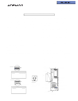
SETTING RESPONSE TIME and SENSITIVITY 1. Set response time using the DIP switches (use the tip of a pen/pencil). SW1 sets a response time of 1ms (milliSec.), SW5 sets a response time of 20ms. For a response time of 0.5ms, set all DIP switches to OFF (see Table 1). 2. Set the pulse count jumper (see Table 2). The pulse count is reset 3 seconds after the first pulse detected. There is an LED on the PCB which flashes rapidly on transmission. NOTE: Make the device highly sensitive for the purpose of enrolling the shock sensor loop (TB1) into the system (turn SW. 1 on and put jumper on J1). After the device has been enrolled, adjust settings as described in steps 1 and 2 above. "ENROLLING" THE TRANSMITTER SERIAL NUMBER Each 5819 Shock Processor has a unique, factory set serial number (assigned during manufacture) that must be "enrolled" by the QED control before usage in the system. In addition, each zone (loop) of the transmitter must also be programmed at the control panel during installation. When programming, note the following: • The battery must be installed before "enrolling". • Assign each loop to an individual zone number and assign Input Type = 3 (Supervised RF). Loop 1 = built-in shock sensor Loop 2 = built-in magnetic reed switch Loop 3 = externally wired, closed circuit contact • Transmit from the unit when prompted by activating any of its loops or tamper switch as follows: Loop 1: Flip the unit upside down, then right side up to activate the sensor. Loop 2: Bring the magnet close to the reed switch, then pull the magnet away to open and close the reed. Loop 3: Open and close the contact according to its instructions. You can also manually enter the unit's serial number. • Test the unit after "enrolling" into the system using the QED control's test procedure. BATTERY INSTALLATION/REPLACEMENT 1. Remove the transmitter's cover as described in Mounting Step 1. 2. Observe correct polarity and insert the battery provided into the battery holder (see Diagram). 3. Replace the cover, engage the hooks along one edge and snap shut. Do not bend the antenna. NOTE: Replace with 3V Lithium battery only: Panasonic CR123A, Duracell DL123A, Sanyo CR123A, Varta CR123A, or ADEMCO 466 BATTERY CAUTION: Risk of fire, explosion and burns. Do not recharge, disassemble, heat above 212° F (100° C) or incinerate. Dispose of used batteries promptly. Keep away from children. UNIT DIMENSIONS 4.8" H x 1.5" W x 1" D TO THE INSTALLER Regular maintenance and inspection (at least annually by the installer and frequent testing by the user are vital to continuous satisfactory operation of any alarm system. The installer should assume the responsibility of developing and offering a regular maintenance program to the user, as well as acquainting the user with the proper operation and limitations of the alarm system and its component parts. Recommendations must be included for a specific program of frequent testing (at least weekly) to insure the system's operation at all times. REFER TO THE INSTALLATION INSTRUCTIONS FOR THE QED RECEIVER/CONTROL WITH WHICH THIS DEVICE IS USED FOR WARRANTY INFORMATION, AND FOR DETAILS REGARDING THE LIMITATIONS OF THE ENTIRE ALARM SYSTEM. àN7491-1V1zä N7491-1V1 5/ 98 165 Eileen W ay, Syosset, New York 11791 Copyright © 1997 Pittway Corporation
-
 1
1 -
 2
2
 |
 |
