Honeywell 5894PI Installation Instructions - Page 2
Pulse Processing Option, Programming, Installation, Radio Transmission Path Check, Mounting, Lens - manual
 |
UPC - 781410691292
View all Honeywell 5894PI manuals
Add to My Manuals
Save this manual to your list of manuals |
Page 2 highlights
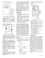
To program the detector, place the LED jumper in the TEST position (see Figure 4), the Pulse Count jumper in the STD position (see Figure 5), batteries installed and cover on. Temporarily cover the lens (a cloth will do) to prevent any activation by the detector. When prompted for the device's serial number, you may either manually enter it or transmit from the unit (remove the cloth cover and motion your hand over the lens to activate the detector). Refer to the control panel installation instructions for programming details. Remove the LED jumper to disable the LED (NORMAL position). 2. Use the mounting plate to mark the mounting holes on the mounting surface (See Figure 7). Figure 4. Printed Circuit Board (PCB) Programming Note: If you have not programmed the detector's ID into the system (i.e., this is an initial detector installation), refer to the PROGRAMMING section below and perform the ID enrolling procedure before mounting or testing the detector. PULSE PROCESSING OPTION See Figure 4 for location of Pulse Processing selection jumper link. Figure 5. Pulse Processing Options Intermediate Pulse Processing (INT) [High Sensitivity]: This setting is recommended for any location where an intruder is expected to cover only a small portion of the protected area. The detector tolerates normal environments on this setting. Note: INT pulse processing is NOT recommended for pet immune applications. Standard Pulse Processing (STD) [Medium Sensitivity]: This setting is the recommended for most applications. The detector tolerates environmental extremes on this setting. Note: STD pulse processing is recommended for pet immune applications. Harsh Pulse Processing (HARSH) [Low Sensitivity]: This setting is recommended for the severest of environments and should only be used in locations where an intruder is expected to cover moderate to large portions of the protected area. PROGRAMMING You must enroll the detector's ID during installation of the system. You should program the 5894PI as an "RF" type unit (i.e., supervised RF), and the "Loop" number as "1." INSTALLATION Installation Hints • Do not install where the detector is exposed to direct sunlight or directly above strong sources of heat. • Make sure the detection area does not have obstructions (curtains, screens, large pieces of furniture, plants, etc.) that may block the pattern of coverage. • Avoid locating a unit in areas that contain objects likely to produce a rapid change in temperature, such as central heating, radiators, or ducts (or heaters of any kind), air conditioners, open flame, etc. • Do not mount on an unstable surface. RADIO TRANSMISSION PATH CHECK Verify that a strong transmission path between the 5894PI and the system's Receiver/Control exists before permanently mounting the detector. Do this by performing the Walk Test (described later) with the detector temporarily mounted in its proposed location. The 5894PI will transmit when sensing motion (such as a person waving an arm or walking into an area). Sometimes, moving the detector only a few centimeters means the difference between a strong and weak transmission path. Experiment until you are satisfied that the location provides the strongest transmission path, yet is still practical for the protection pattern desired. This test also verifies that the detector has been correctly programmed into the system. MOUNTING Mount the unit to a firm vertical surface (flat on a wall or in a corner). 1. Hold the mounting plate in one hand and slide the detector in the direction of the arrows molded on the outside of the plastic housing. Figure 6. 5984PI Side View Figure 7. Mounting Plate 3. Install the detector mounting plate using the hardware kit provided. 4. Align the detector base over the mounting locks on the mounting plate, press the detector onto the locks and slide down until firmly locked into position. Note: For battery replacement or service, slide the mounted detector in the direction of the arrows molded into the side of the detector to dismount the detector. Note: Mounting Accessories also available: SMB-10 Swivel Mount Bracket (P/N 0-000-110-01) SMB-10T Tampered Swivel Mount Bracket (P/N 0-000-155-01) SMB-10C Ceiling Mount Bracket (P/N 0-000-111-01) Note: Swivel Mount Brackets should not be used in pet applications. LENS MASKING The masking strips that have been supplied (Masking Kit P/N K9086) are designed for application to one or more lens segments to produce a protection pattern that suits the particular requirements of the protected area. Individual masking strips have been provided for each of the lens segments on the standard lens supplied with the PIR. Simply peel off the appropriate pressure-sensitive adhesive strip(s) and apply over the desired lens segment(s). Be sure to affix the masking strips to the inside of the lens (not the outer, smooth side). Each lens segment that is masked results in the elimination of one zone of protection from the coverage pattern. By masking segments of the lens, you can adjust the coverage to suit the area to be protected, or eliminate coverage from areas where you anticipate environmental disturbances that might reduce the PIR's stability (a heater or other heat-producing object for example). Important: When hallway pattern masking is used, be sure the PIR is set for instant response. Page 2
-
 1
1 -
 2
2 -
 3
3 -
 4
4
 |
 |
