Honeywell 6160 Setup Guide - Page 2
K3590-ADV4_Š - alpha keypad
 |
UPC - 781410342088
View all Honeywell 6160 manuals
Add to My Manuals
Save this manual to your list of manuals |
Page 2 highlights
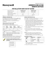
ARMED READY NOTE: TO REMOVE CASE BACK PUSH IN THE TWO MOUNTING SNAPS LOCATED ALONG THE BOTTOM OF THE KEYPAD AND LIFT UP. FUNCTION KEY LABELS A set of adhesive-backed labels with some typical function symbols (i.e., fire, police, personal emergency, etc.) is provided. These labels can be placed on or next to the keys to identify each key's function for the end user (as determined by the control panel's capability and programming; see the control's instructions). OPERATING THE KEYPAD For operating instructions, see the User Guide for the control panel used with this keypad. SPECIFICATIONS RETAINING SNAPS LOCKING TAB Figure 1. Removing the Case Back SETTING THE KEYPAD ADDRESS The keypad can either be set for an address of 00-30, or to the non-addressable mode (31). The keypad's default address is 31. To change the keypad's address, do the following: 1. Enter address mode: Power up the keypad. Within 60 seconds of power-up, press and hold down the [1] and [3] keys at the same time for 3 seconds. (If unable to enter address mode, power up and try again.) The current keypad address will be displayed, and the cursor will be under the "tens" digit. If 10 seconds have passed with no key entry, the keypad automatically exits address mode. You must power down, power up and start address mode again. NOTE: The keypad will not enter address mode if the panel to which it is connected is in programming mode. 2. Set the current address to "00": Press [0] to clear the current "tens" digit. The cursor will move to the "ones" digit position. Press [0] to clear the current "ones" digit. The cursor will move back to the "tens" digit position. 3. Enter the keypad's address: Enter the proper "tens" digit of the keypad's address. The cursor will move to the "ones" digit position. Enter the proper "ones" digit of the keypad's address. Note that address "31" sets the keypad to non-addressable mode. 4. Exit address mode: Press [Ã] to save the displayed address and exit address mode. 6150-006-V0 Physical: 6150: 6160: Displays: 6150: 6160: Sounder: 6150: 6160: Voltage: Current: 6150: 6160: NFPA-72 4-7/8"H x 6-1/4"W x 1"D 5-5/16"H x 7-3/8"W x 1-3/16"D Fixed-Word LCD (backlit). 2 x 16 alpha-numeric supertwist LCD, backlit. Piezo-electric (fire alarm is loud, pulsing single tone; (all Keypads) burglary alarm is loud, continuous, dual tone). Speaker. 12VDC (power-limited) 70mA (ARMED LED lit, LCD backlight and sounder on), reduces to 40mA when panel is operating in standby mode (backlight off). 150mA (ARMED LED lit, LCD backlight and sounder on), reduces to 40mA when panel is operating in standby mode (backlight off). Compliant. VIEWING THE KEYPAD ADDRESS Press and hold down the [1] and [3] keys at the same time for about 3 seconds. The current address is displayed. No key entry is allowed. Press any key to exit or wait 10 seconds to exit viewing mode. REFER TO INSTALLATION INSTRUCTIONS FOR THE CONTROL PANEL WITH WHICH THIS DEVICE IS USED FOR WARRANTY INFORMATION AND LIMITATIONS OF THE ENTIRE ALARM SYSTEM. For the latest warranty information, please go to: http://www.security.honeywell.com/hsc/resources/wa/index.html 2 Corporate Center Drive, Suite 100 P.O. Box 9040, Melville, NY 11747 Copyright © 2009 Honeywell International Inc. www.honeywell.com/security K3590-ADV4_Š K3590-ADV4 2/09 Rev. A
-
 1
1 -
 2
2
 |
 |