Honeywell 6160V Installation Guide - Page 1
Honeywell 6160V - Ademco Talking Alpha Display Keypad Manual
 |
UPC - 781410414808
View all Honeywell 6160V manuals
Add to My Manuals
Save this manual to your list of manuals |
Page 1 highlights
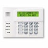
K0022V2 12/01 Rev. B ADEMCO 6150V & 6160V Voice Remote Keypads INSTALLATION AND SETUP GUIDE GENERAL INFORMATION The ADEMCO 6150V and ADEMCO 6160V are addressable remote keypads designed for use with ADEMCO control panels and provide the following features: • Backlit Display • • Programmable Function • Keys • • Built-in Sounder Notes: Voice Chime Voice Status Message Center • When used with the ADEMCO VISTA-15P/VISTA20P control panels, address 16 must be assigned to the first keypad. Additional keypads must be assigned to address 17 - 23. Refer to Setting The Keypad Options. • Keypad keys are continuously backlit for convenience. • Permanent display backlighting is an option on some controls (refer to the control panel's instructions for details). • Voice Chime should only be enabled when used with control panels that support the "chime by zone" mode (e.g., VISTA-15P/VISTA-20P). This mode must be enabled at the control panel. Refer to the control panel's installation and setup guide for information on how to program the chime mode. • Use only zone descriptors supported by this keypad. If using zone descriptors not supported by this keypad, you must turn voice status and voice chime off. Table 1 is a list of applicable zone descriptors and index entries. Refer to the control panel's installation and setup guide for information about how to program zone descriptors. KEYPAD DISPLAYS AND LEDS The keypads have the following display features: Model 6150V 6160V Fixed Word Display X 2-Line Alpha Display X 2-Digit Zone Identifier X Custom Zone Descriptors X The following table identifies the keypad's LEDs and associated functions: LED ARMED READY MESSAGE Function Lights red when the system is armed in any mode. Lights green when the system is "ready" to be armed. Flashes red when message waiting or lights red (steady) when in record mode. PROGRAMMABLE FUNCTION KEYS The keypad's programmable function keys [A, B, C] are normally used for keypad panic functions, but they can be programmed for other special functions instead. If they are programmed for other special functions, the associated keypad key pairs still provide the respective panic alarm (if programmed). Refer to the control panel's Installation & Setup Guide for details. Function Keys A B C D Equivalent Key Pairs [1] and [*] [*] and [#] [3] and [#] NONE • Function keys must be held down for at least 2 seconds to activate the programmed function. • If functions other than panics are assigned to the programmable function keys, programmed panics must be initiated by pressing the programmed key pair. FUNCTION KEY LABELS A set of adhesive-backed labels with some typical function symbols (i.e., fire, police, personal emergency, etc.) is provided. These labels can be placed on or next to the keys to identify each key's function for the end user (as determined by the capability and programming of the control panel; refer to the installation and setup guide for the control panel). A B ARMED READY MESSAGE C MIC D 1 OFF RECORD 4 MAX 2 AWAY VOLUME 5 TEST 3 STAY PLAY 6 BYPASS 7 INSTANT 8 CODE 9 CHIME READY STATUS 0 # VOICE FUNCTION SIDE VIEW 6160V-001-V1 MOUNTING RELEASE SNAPS (Remove case back by pushing up the 2 "snaps" along the keypad's bottom edge and pulling the case apart.) WIRING AND INSTALLATION Keypads can be surface mounted using drywall anchors or to a single- or double-gang electrical box. 1. Remove the case back by pushing up the two "snaps" along the keypad's bottom edge and pulling the case apart. See diagram above. 2. Route wiring from the control panel through the opening in the case back. 3. Mount the case back to a wall or electrical box. 4. Wire directly from the keypad's terminal block to the terminal block on the control board. (See Wiring Table that follows.) Wiring Table (All Keypads) Keypad ° G Control Panel Data In Wire Color Green - - Aux Pwr (GND) Black + + Aux. Pwr ± Y Data Out Red Yellow 5. Re-attach the keypad to the case back. 6. Remove clear protective film from LEDs (6160V only).
-
 1
1 -
 2
2
 |
 |
