Honeywell 6165EX Installation Instructions
Honeywell 6165EX Manual
 |
View all Honeywell 6165EX manuals
Add to My Manuals
Save this manual to your list of manuals |
Honeywell 6165EX manual content summary:
- Honeywell 6165EX | Installation Instructions - Page 1
Honeywell Power Products 12 Clintonville Road Northford, CT 06472 http://www.honeywellpower.com HPS3 PRODUCT INSTALLATION DOCUMENT PN 52231:B 11/09/2004 ECN 04-580 HPS3: - Honeywell 6165EX | Installation Instructions - Page 2
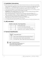
4 Installation Instructions The HPS3 should be installed in accordance with the National Table.) NOTE: For additional information • Visit our website: http://www.honeywellpower.com • Contact Technical Support: (800) 627-3473 • Email us: [email protected] 2 HPS3 Power Supply/Charger -
-
 1
1 -
 2
2
 |
 |
HPS3 PRODUCT INSTALLATION DOCUMENT
PN 52231:B
11/09/2004
ECN 04-580
Honeywell Power Products
12 Clintonville Road
Northford, CT 06472
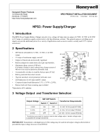
HPS3: Power Supply/Charger
1 Introduction
The HPS3 Power Supply/Battery Charger converts a low voltage AC input into an output of 6 VDC, 12 VDC or 24 VDC
@ 2.5 amps of continuous supply current (refer to the Specifications section).
This general purpose switching power
supply can provide additional power for a variety of applications such as access control, security and CCTV system
accessories.
2 Specifications
•
DIP Switch selectable for 6 VDC, 12 VDC or 24 VDC
output.
•
2.5 amps of continuous supply current*.
•
Output is filtered and electronically regulated.
•
Built-in charger for sealed lead acid or gel type batteries.
•
Maximum charge current of 400 mA.
If a battery charger is used, subtract max charge current of
400 mA from total to determine allowable load.
•
Automatically switches to stand-by battery upon AC fail.
•
Battery protected from short circuits.
•
Thermal and short circuit protection with auto reset.
•
LED indicators for AC input and DC output.
•
Compact design (board dimension 3.5"L x 3.0"W x 2.0"H).
•
Battery leads and foam mounting tape included.
*Specified at 25ºC ambient.
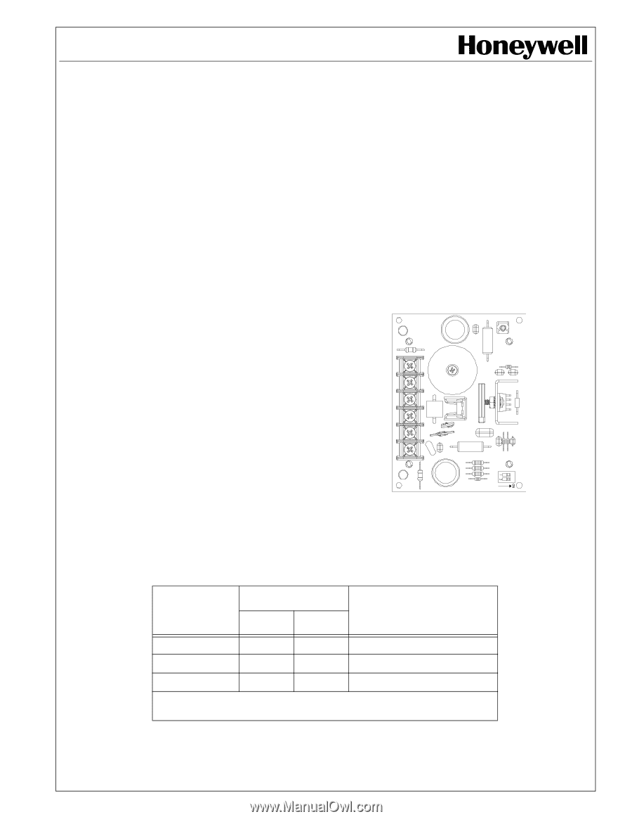
3
Voltage Output
and Transformer Selection:
IMPORTANT!
Transformers with higher power (VA) ratings may be used for all output voltages selected above
provided the input voltage does not exceed 28VAC.
Output Voltage
SW1 DIP Switch
Transformer Requirements
Switch 1
Switch 2
6 VDC
ON
OFF
16
VAC / 40 VA (model HTP1640)
12 VDC
OFF
OFF
24
VAC / 50 VA (model HTP2450)*
24 VDC
OFF
ON
28
VAC / 100 VA / (model HT28100)
*Transformers are sized for maximum load at rated voltage output.
Greater voltage output
is possible with a larger transformer.
DC +
DC –
BAT +
BAT –
AC
AC
HPS3.wmf
TB1
DC LED
AC LED
SW1