Honeywell 6165EX Installation Instructions - Page 2
Installation Instructions, LED Indicators, Terminal Identification
 |
View all Honeywell 6165EX manuals
Add to My Manuals
Save this manual to your list of manuals |
Page 2 highlights
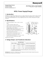
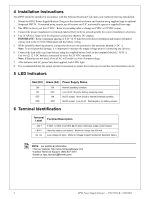
4 Installation Instructions The HPS3 should be installed in accordance with the National Electrical Code and Local Authority Having Jurisdiction. 1. Mount the HPS3 Power Supply/Battery Charger in the desired enclosure and location using supplied tape or optional Snaptrack HST34. If mounted using screws, use #6 screws and 3/8" non-metallic spacer or supplied foam tape. 2. The HPS3 is factory set for 12 VDC. Refer to preceding table to change to 6 VDC or 24 VDC output. 3. Connect the proper transformer to terminals labeled [AC] (refer to preceding table for correct transformer selection). 4. Use 18 AWG or larger wire for all power connections (battery, DC output). IMPORTANT! Keep a minimum spacing of 0.25" (6.35 mm) between all power-limited and nonpower-limited wiring such as the 115VAC/60Hz Input and the battery wiring. 5. While carefully observing polarity, connect the devices to be powered to the terminals labeled [+ DC -]. Note: To avoid potential damage, it is important to measure the output voltage prior to connecting any devices. 6. Connect the lead acid or gel type battery using the supplied battery leads to the terminals labeled [+ BAT -]. Use two (2) 12 VDC batteries connected in series for 24 VDC operation. Note: If batteries are not used, a loss of AC will result in a loss of output voltage. 7. After batteries and AC power have been applied, both LEDs light. 8. It is recommended that the output current be measured to ensure that it does not exceed the rated maximum current. 5 LED Indicators Red (DC) Green (AC) Power Supply Status ON ON OFF OFF ON OFF ON OFF Normal operating condition. Loss of AC, Stand-by battery supplying power. No DC output. Short circuit or thermal overload condition. No DC output. Loss of AC. Discharged or no battery present. 6 Terminal Identification Terminal Label Function/Description - DC + + BAT - AC AC 6 VDC, 12 VDC or 24 VDC @ 2.5 amp continuous supply current output. Stand-by battery connections. Maximum charge rate 400 mA. Low voltage AC input. (Refer to Voltage Output/Transformer Selection Table.) NOTE: For additional information • Visit our website: http://www.honeywellpower.com • Contact Technical Support: (800) 627-3473 • Email us: [email protected] 2 HPS3 Power Supply/Charger - P/N 52231:B 11/09/2004
-
 1
1 -
 2
2
 |
 |
