Honeywell CT3611 Owner's Manual
Honeywell CT3611 Manual
 |
View all Honeywell CT3611 manuals
Add to My Manuals
Save this manual to your list of manuals |
Honeywell CT3611 manual content summary:
- Honeywell CT3611 | Owner's Manual - Page 1
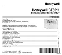
Honeywell CT3611 PROGRAMMABLE THERMOSTAT Seven Day Programmable Heat Pump Low Voltage (20 to 30 Vac) Thermostat and Wallplate Model CT3611 OWNER'S GUIDE Para pedir estas instrucciones en español, llame al 1-800-468-1502. Pour obtenir ce ode demploi en français, composer le 1-800-468-1502. - Honeywell CT3611 | Owner's Manual - Page 2
and comfortable with your Honeywell thermostat - the state of the art in home comfort controls. Read these instructions carefully. Failure to follow these instructions can damage the product or cause a hazardous condition. MERCURY NOTICE If this thermostat is replacing a control that contains - Honeywell CT3611 | Owner's Manual - Page 3
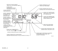
TIME AND DAY RUN PROGRAM RETURNS THERMOSTAT TO NORMAL OPERATING MODE Run Program Set Current Day/Time Time Wake Set Program Leave Return DIGITAL DISPLAY RAISES TEMPERATURE SETTING LOWERS TEMPERATURE SETTING DISPLAYS CURRENT HEAT/COOL TEMPERATURE SETTING PROGRAM PERIODS WAKE/LEAVE/RETURN - Honeywell CT3611 | Owner's Manual - Page 4
DISPLAYS EITHER CURRENT TIME OF DAY OR PROGRAM TIMES SHOWS THERMOSTAT IS IN THE SET DAY/TIME MODE SHOWS WHEN THERMOSTAT IS IN THE PROGRAMMING MODE SHOWS VACATION HOLD DURATION SHOWS TEMPERATURE SETTING CHANGED FOR THIS PROGRAM PERIOD SHOWS THERMOSTAT IS "CALLING" FOR EMERGENCY OR AUXILIARY HEAT - Honeywell CT3611 | Owner's Manual - Page 5
FOR INSTALLATION q This thermostat is designed to work with multistage heat pumps (heat pumps with Auxiliary and/or Emergency Heat). Check Table 1 in Step 4 to make sure the CT3611 is compatible with your system. If you have compatibility questions, contact Honeywell at www.honeywell.com/yourhome - Honeywell CT3611 | Owner's Manual - Page 6
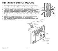
the wallplate over the holes. Pull the wires through the wiring opening. Loosely insert mounting screws into each of the holes. q Level the wallplate if desired. Thermostat functions properly when not level. q Tighten mounting screws. WALL WIRES THROUGH WALL WALL ANCHORS (2) M18701 69-1081 - Honeywell CT3611 | Owner's Manual - Page 7
local heating/air-conditioning contractor. Refer to the labels you placed on the wires when you removed the old thermostat (see illustration). q Match the letter of your old thermostat wire with the corresponding terminal letter on your new thermostat. Refer to Table 1. q For wiring diagrams, if - Honeywell CT3611 | Owner's Manual - Page 8
Honeywell. b If the old thermostat had separate wires on both the V and VR terminals, some system modification is required. Call your local heating and cooling contractor for assistance. c If the old thermostat had wires on W1, Y1 and W2 terminals, then remove the CT3611 factory-installed jumper - Honeywell CT3611 | Owner's Manual - Page 9
STEP 5. MOUNT THE THERMOSTAT STEP 6. CUSTOMIZE YOUR THERMOSTAT Your Honeywell CT3611 thermostat comes preset to the most commonly used settings. The settings are: - Auxiliary and/or Emergency Heat type. - Smart Response™ technology on. - Temperature °F. - 12-hour clock format. You can change any or - Honeywell CT3611 | Owner's Manual - Page 10
6 = Gas or oil forced air furnace. - 9 = Electric heat system (preset). To change your Emergency Heat type: q Press until display shows your Emergency Heat type. q Press Time to move to next feature or Run Program to return to main display. Smart Response™ Technology (Feature Number 13) Smart - Honeywell CT3611 | Owner's Manual - Page 11
options are: - 0 = 12-hour clock (preset). - 1 = 24-hour clock. To change time format: q Press once. q Press Run Program to return to main display. Factory Set Function (Feature Number 37) Do not change this setting. M13344 M13345 STEP 7. SET THE CLOCK M13346 Set Current Day and Time NOTE - Honeywell CT3611 | Owner's Manual - Page 12
settings. The thermostat displays day, time, program period, temperature, system and fan settings. There is an individual key for each of the four program periods: Wake -The program period when you want the house at a comfortable temperature when you get up and while you get ready for work or school - Honeywell CT3611 | Owner's Manual - Page 13
thermostat default settings are shown in parentheses ( ). Table 2. Personal Programming 82°F/28°C) a Your heating setpoints cannot be higher Program the First Day Start by programming the wake time and temperature for one day. q Press and release Wake . q Press Day until the desired day displays - Honeywell CT3611 | Owner's Manual - Page 14
range is 40°F to 90°F (7°C to 31°C) for heating and 45°F to 99°F (9°C to 37°C) for cooling. q Press Heat/Cool Settings to switch between setpoints. NOTE: Program times are the same for heating and cooling. q Press or until the display shows the desired temperature setpoint. q Press , Leave - Honeywell CT3611 | Owner's Manual - Page 15
OPERATING YOUR THERMOSTAT Change Temperature Setting Until the Next Program Period (Temporary Change) q Press or until the screen shows the desired temperature setting. NOTE: The temporary temperature setting is displayed for about 3 seconds and then the room temperature is displayed. Temporary - Honeywell CT3611 | Owner's Manual - Page 16
switch to the desired position (Heat or Cool). q Press Hold Temp then or to change your setting if desired. (The display changes from showing the setpoint temperature to room temperature after approximately three seconds). q To cancel "Hold" press Run Program . Change the Temperature Setting - Honeywell CT3611 | Owner's Manual - Page 17
function. STEP 10. SET THE FAN AND SYSTEM SWITCHES First set the fan switch. Fan On: The fan runs continuously. Use for improved air circulation or for more efficient central air cleaning. (In a heat-only system, fan runs continuously only if fan relay is connected to the G thermostat terminal - Honeywell CT3611 | Owner's Manual - Page 18
it is not. • Make sure terminal C is connected to the system transformer common. • Make sure circuit breaker is not tripped-reset the circuit breaker. • Make sure the wiring between the thermostat and HVAC equipment has no broken wires-replace any broken wires. Temperature settings will not change - Honeywell CT3611 | Owner's Manual - Page 19
separate wire is hooked to the L terminal it can be connected to a system monitor. If so, the light being on indicates a problem with the heat pump. Contact your local heating and cooling contractor. Toll-Free Customer Assistance Please read and follow the provided instructions for this thermostat - Honeywell CT3611 | Owner's Manual - Page 20
1 IF In Recovery IS DISPLAYED, PRESS TO SEE THE COMFORT SETPOINT. M18591 Recovery. Honeywell does not recommend this because the auxiliary heat comes on once the program time begins and run continuously until the setpoint is reached. See Step 6. Customize Your Thermostat. 69-1081-3 20 - Honeywell CT3611 | Owner's Manual - Page 21
. L1 (HOT) 2 NEVER ATTACH WIRES TO BOTH THE O AND B TERMINALS. SEE WIRE WALLPLATE TERMINALS SECTION FOR MORE DETAILS. M15110B Typical hookup of CT3611 with isolated stage-one heating and cooling connections. THERMOSTAT BL C R W2 E W1Y O G 2 EQUIPMENT MONITOR AUX. HT. RELAY FAN RELAY - Honeywell CT3611 | Owner's Manual - Page 22
excluding battery, to be free from defects in the workmanship or materials, under normal use and service, for a period of one (1) year from the date of purchase by the consumer. If, at any time during the warranty period, the product is defective or malfunctions, Honeywell shall repair or replace it - Honeywell CT3611 | Owner's Manual - Page 23
have other rights which vary from state to state. If you have any questions concerning this warranty, please write our Customer Relations Center, Honeywell Inc., 1885 Douglas Dr. N., Golden Valley, MN 55422-3992, or call 1-800-468-1502, Monday-Friday, 7:00 a.m. to 5:30 p.m., Central time. In Canada - Honeywell CT3611 | Owner's Manual - Page 24
Home and Building Control Honeywell 1985 Douglas Drive North Golden Valley, MN 55422 Home and Building Control Honeywell Limited-Honeywell Limitée 35 Dynamic Drive Scarborough, Ontario M1V 4Z9 69-1081-3 J.H. Rev. 11-01 Printed in U.S.A. on recycled paper containing at least 10% post-consumer
-
 1
1 -
 2
2 -
 3
3 -
 4
4 -
 5
5 -
 6
6 -
 7
7 -
8
-
9
-
10
-
11
-
12
-
13
-
14
-
15
-
16
-
17
-
18
-
19
-
20
-
21
-
22
-
23
-
24
 |
 |
69- 1081- 3
OWNER°S GUIDE
fi U.S. Registered Trademark
Copyright ' 2001 Honeywell °
°All Rights Reserved
Honeywell CT3611
PROGRAMMABLE THERMOSTAT
Seven Day
Programmable Heat Pump
Low Voltage (20 to 30 Vac) Thermostat and Wallplate
Model CT3611
Para pedir estas instrucciones en espaæol, llame al 1-800-468-1502.
Pour obtenir ce ode demploi en fran±ais, composer le 1-800-468-1502.
Table of Contents
Step 1. Prepare for Installation
..................................................................................................................................
5
Step 2. Remove Old Thermostat
...............................................................................................................................
5
Step 3. Mount thermostat Wallplate
...........................................................................................................................
6
Step 4. Wire Wallplate Terminals
...............................................................................................................................
7
Step 5. Mount the Thermostat
...................................................................................................................................
9
Step 6. Customize Your Thermostat
..........................................................................................................................
9
Step 7. Set the Clock
.................................................................................................................................................
11
Step 8. Programming
.................................................................................................................................................
12
Step 9. Operating Your Thermostat
...........................................................................................................................
15
Step 10. Set the Fan and System Switches
..............................................................................................................
17
If You Have a Problem
...............................................................................................................................................
18
Smart Response™ Technology
.................................................................................................................................
20
Wiring Diagrams
........................................................................................................................................................
21