Honeywell DT7235 User Guide - Page 1
Honeywell DT7235 Manual
 |
View all Honeywell DT7235 manuals
Add to My Manuals
Save this manual to your list of manuals |
Page 1 highlights
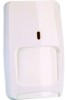
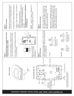
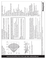
DT-7235/DT-7235T DUAL TEC® Motion Sensor Installation Instructions FRONT HOUSING Housing latch REAR HOUSING AND PCB PCB LED (DS1) LED Enable (Cut or remove LED enable jumper J1* to disable LED) Step 1 Separate the sensor housings and remove Printed Circuit Board (PCB). Use a small screwdriver to unfasten the housing latch and separate the sensor housings. Push outward on the PCB latch to lift the PCB out of the housing. Step 2 Mount the sensor. Break out the mounting/wiring knockouts and mount the sensor in an appropriate location. An ideal location meets the following objectives: • Allows a clear line-of-sight to all areas to protect. • Does not directly face windows. • Avoids close proximity to moving machinery, fluorescent lights, and heating/cooling sources. • See Special Instructions for installations containing pets. Remove look-down mask for non-pet applications. NOTE: maximum range is obtained at a mounting height of 2.3 m (7'6"). Step 3 Wire the sensor. Knockout Observing the proper polarity, wire the unit as shown in the illustration below, use 1.02 to 0.64 mm (18 to 22 AWG) wire. PCB latch DT-7235 Power Alarm 25 mA 500 mA 7.5-16 VDC 30 VDC (UL: 8.9-14.5 VDC) TB1 Step 4 Walk-test the sensor. After returning the PCB to the rear housing, reassemble the sensor housing. Apply power to the sensor and begin walktest when the red LED is off. Walk across the detection area at the ranges to be covered. The red LED should indicate an alarm condition after 2 to 4 normal steps. When there is no motion in the detection area the LED should be off. TB2 DT-7235T Terminal Block (TB1) * J1 may be located in either location indicated in the above illustration. DT-7235T Tamper 50 mA 24 VDC TB2 TT Power Alarm 25 mA 500 mA 7.5-16 VDC 30 VDC (UL: 8.9-14.5 VDC) TB1
-
 1
1 -
 2
2
 |
 |
