Honeywell F500A1000 Owner's Manual - Page 3
Planning The Installation - whole house hepa air cleaner
 |
View all Honeywell F500A1000 manuals
Add to My Manuals
Save this manual to your list of manuals |
Page 3 highlights
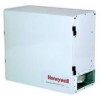
F500 WHOLE HOUSE/ LIGHT COMMERCIAL HEPA FILTRATION SYSTEM Filter (in in.) Carbon-Odor Filter (24 x 12) Pleated Prefilter (24 x 12 x 2) HEPA Filter (24 x 12) Table 1. Replacement Media Recommendations. Replacement Interval Part Number Normal Light Duty 32006026-001 3 months 4 months 32006027-001 12 months 16 months 32006028-001 3 years 5 years PLANNING THE INSTALLATION Selecting Mounting Position and Location The F500 can be suspended from exposed ceiling joists or the ceiling surface, or it can be floor-mounted. 1. Install the F500A in a conditioned space or the F500B in an unconditioned space using these guidelines. 2. Plan the unit location to minimize duct lengths. 3. Locate an existing electrical outlet with the appropriate current rating to plug in the power cord. (If an outlet is not available, have a qualified electrician install one.) 4. Choose a location that is readily accessible for checking and replacing the filter. (Allow at least 26-1/2 in. (673 mm) clearance in front of the unit.) Planning Ducting The F500 can be mounted to the whole-house forced air system using a bypass configuration or can be independently ducted to stand alone. See Fig. 2, 3, and 4 for typical installations. • The Whole House/Light Commercial HEPA air cleaner has 4 in. x 10 in. duct flanges to easily attach the external ductwork. • The intake port can be moved to a more convenient location, if necessary: - Simply cut a new 4 in. x 10 in. hole in the desired location and block off the old hole. - Reattach the duct flange over the new hole. • A transition can be used to connect round ducting to the Whole House/Light Commercial HEPA System. - Keep duct sizes as large as possible throughout the installation (8 in. minimum diameter ducting is recommended). - Keep intake and exhaust duct runs as short as possible with few bends or elbows. • The F500 can be installed with a heat recovery ventilator. See Fig. 4. 120 VAC 60 HZ SUPPLY WITH GROUND RETURN AIR S688A1007 SAIL SWITCH (OPTIONAL) F500 HIGH EFFICIENCY AIR CLEANER AIR HANDLER (FURNACE) M20263A Fig. 2. Typical F500 bypass installation. F500 15 AMP LIGHT SWITCH 120 VAC 60 HZ SUPPLY WITH GROUND M20579 Fig. 3. Typical F500 independent installation. 3 68-0263-2
-
 1
1 -
 2
2 -
 3
3 -
 4
4 -
 5
5 -
 6
6 -
 7
7 -
 8
8
 |
 |
