Honeywell HCCM474M User Manual - Page 11
CONTROLS AND CONNECTIONS, CONTINUED, Camera Back, continued - cables
 |
View all Honeywell HCCM474M manuals
Add to My Manuals
Save this manual to your list of manuals |
Page 11 highlights
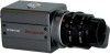
CONTROLS AND CONNECTIONS, CONTINUED Camera Back, continued 1. Lens switch Used to switch between DC and Video lenses. 2. Lens connector When using an auto-iris lens, connect the lens cable to this connector. 3. Video output connector BNC connector that outputs a composite video signal. 4. Power indicator Indicator lights when the camera is powered. 5. Setup buttons Used when setting up and adjusting the camera with the on-screen menu. 6. Power input terminal Use only 24Vac or 12Vdc UL listed class 2 power supply. REV. B 11 HCMU000878 12/29/03
-
 1
1 -
2
-
3
-
4
-
5
-
 6
6 -
 7
7 -
 8
8 -
 9
9 -
 10
10 -
 11
11 -
 12
12 -
 13
13 -
 14
14 -
 15
15 -
 16
16 -
17
-
18
-
19
-
20
-
21
-
22
-
23
-
24
-
25
-
26
-
27
-
28
-
29
-
30
-
31
-
32
-
33
-
34
-
35
-
36
-
37
-
38
-
39
-
40
-
41
 |
 |

REV.
B
11
HCMU000878
12/29/03
CONTROLS AND CONNECTIONS, CONTINUED
Camera Back, continued
1.
Lens switch
Used to switch between DC and Video lenses.
2.
Lens connector
When using an auto-iris lens, connect the lens cable to this connector.
3.
Video output connector
BNC connector that outputs a composite video signal.
4. Power
indicator
Indicator lights when the camera is powered.
5.
Setup buttons
Used when setting up and adjusting the camera with the on-screen menu.
6
.
Power input terminal
Use only 24Vac or 12Vdc UL listed class 2 power supply.