Honeywell HP400ULM Installation Instructions - Page 3
LED Indications, Alarm/Trouble Output, Cascade Connection, Power Board Connections, Power Up - security
 |
View all Honeywell HP400ULM manuals
Add to My Manuals
Save this manual to your list of manuals |
Page 3 highlights
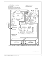
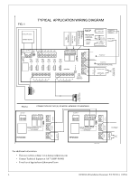
b) JL OFF will cause the unit to latch ON until manually reset. Install the 2.2K Ohm (EOL) resistor provided at a Key Switch or Push Button to perform this manual reset operation and to supervise this connection as shown in Fig 1a. 6. Alarm/Trouble Output a) Power Fail: When DC Power fails or PTC activates this will cause the dry contact "Form C" relay to de-energize. b) Fire Alarm: When the FACP activates this will cause the dry contact "Form C" relay to de-energize. 7. Cascade Connection Two (2) or more HPMOM6 units can be connected together as follows; Connect the Fire Alarm relay C and NC terminals from the 1st unit to the "FIRE INTRFC" of the 2nd unit (not polarity sensitive) and remove jumper JR of the 1st unit. If a 3rd HPMOM6 is used, JR must be removed from 2nd unit and so on for each new addition. See Fig. 1a. 8. Power Board Connections Connect the "AC Fail" output "Form C" dry contacts to the monitoring device. In case of AC loss the relay, which is Fail Safe, will de-energize within one (1) minute. Connect the Battery Fail output "Form C" dry contacts to the monitoring device. If a Battery is not connected or improperly connected, the Yellow LED (L3) will turn ON within one (1) minute and the Battery Fault output relay, which is Fail Safe, will de-energize. 9. Power Up When all wiring is complete and checked, switch ON the AC Power. The Green Led (L1) will come ON indicating AC presence and the AC relay will be energized. Connect Battery observing the correct polarity. For 24VDC use the battery link provided to connect the two (2) 12 Volt Batteries in series. Secure the enclosure with the 4 screws and with the Key Lock provided. NOTE: For UL603 or UL294 applications use a Tamper Switch (Catalog number HPVM3 available separately), and included enclosure key lock. Connect the tamper switch NC outputs to monitoring device to notify of enclosure tampering. 4 LED Indications Power Board LED Number L1 L2 L3 L4 L5 Power Board Status When Lit Green LED - AC present Red LED - PTC activated Yellow LED - battery low or disconnected Red LED - DC power failure Red LED - DC output present Distribution Board LED Number L0 L1 - L6 L7 Distribution Board Status When Lit Red LED - Power ON Green LED - PTC activated Yellow LED - FACP alarm activated HP400ULM Installation Document P/N 52390:A 1/05/06 Continued on next page... 3
-
 1
1 -
 2
2 -
 3
3 -
 4
4 -
 5
5 -
 6
6
 |
 |
